Digital diving computers have Canadian origins. Research and development on devices for calculating and managing dives, whether real or simulated in hyperbaric chambers, began in Canada in 1962 at the Canadian Forces Medical Services Institute of Aviation Medicine. This organization would later be incorporated into the Defense and Civil Institute of Environmental Medicine (DCIEM). Most of the theoretical and experimental research on these topics was carried out by the Canadian scientist duo Derek J. Kidd (a Navy surgeon) and Royston A. Stubbs (an Air Force physicist). They developed a theoretical decompression model based on four tissue compartments with half-times of 10, 20, 40, and 80 minutes. In addition to developing this decompression model, research and development also focused on the design and construction of mechanical-pneumatic devices capable of providing the diver or chamber operator with the information necessary for safe dive manageme
These devices, called PDACs or Pneumatic Analogue Decompression Computers (like the pneumatic-analog decompression meters from the Italian company SOS), were produced in various increasingly sophisticated versions throughout the 1960s and into the first half of the 1970s. These devices were used primarily by the Canadian armed forces and research institutions, although a commercial version was produced by SPAR Aerospace Products Ltd., later incorporated into DeHavilland Aircraft of Canada, Ltd. Unfortunately, the various technical and reliability problems encountered on the first models produced, the high manufacturing costs, and the low sales numbers soon led to the end of the production phase, which was limited to only about 450 units.
The main limitations of some of these devices, which were also beginning to spread to the sports diving market at that time, and of which the SOS DCP decompression gauge, launched in 1959, was surely the most successful model, lay in their extreme sensitivity to external conditions such as temperature, vibrations, and shocks, and in the variability of behavior between one instrument and another. These situations often required recalibrations to maintain acceptable accuracy.
The several models developed by DCIEM, having to operate and account for four different tissue compartments, unlike the DCP which was based on a single compartment representing an "average tissue," were highly complex in construction. This complexity can be seen in Fig. 1, which represents the operating scheme of the pneumatic-mechanical device, taken from U.S. patent 3,457,393 filed by Kidd and Stubbs on October 7, 1965, and in Fig. 2, which shows one of the physical prototypes of this unit.
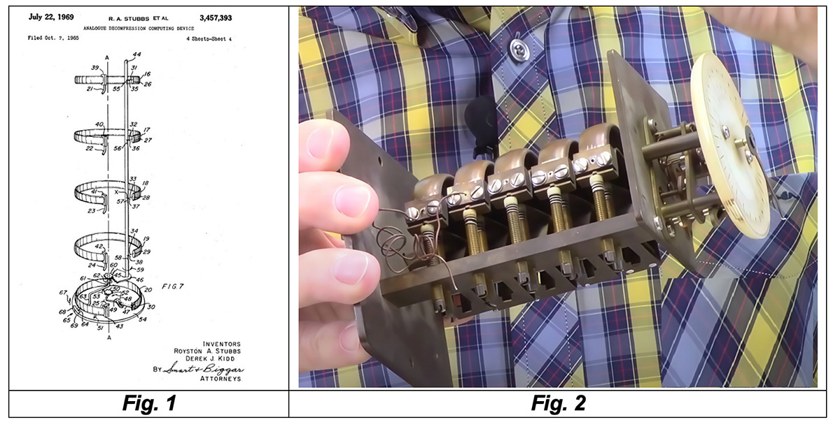  |
The behavior of each of the four tissue compartments was simulated by a mechanism consisting of a Bourdon tube, a pneumatic resistance (orifice or calibrated tube), and a rigid volume. The four mechanisms were connected in parallel to a single shaft equipped with a hand rotating above a depth-indicating dial. This hand indicated the safe ascent depth to the first decompression stop. A fifth Bourdon tube, connected to another mechanism and another hand, showed the current depth of the dive. An additional constructional complexity of the DCIEM decompression meter models was due to the need to supply the several Bourdon tube-sensitive mechanisms with gas (air) at the ambient pressure. The simplest and most effective system was undoubtedly the one proposed by Carlo Alinari for his DCP and further models and showed in the scheme taken from US patent 3,121,333 (see Fig. 3).
The gas (in this case air) at the same ambient pressure was supplied to the sensing element of the decompression meter through a bellows or other flexible volume (SOS decompression meters used small flexible bladders). Not wanting to infringe on the Italian patent, Kidd and Stubbs had to include in their decompression meter a tube that connected the inlets of the Bourdon tubes to the body of the diving regulator, downstream of the air supply valve (see Fig. 4).
 |
Analog electronic devices could offer an alternative to pneumatic ones for simulating tissue compartments in a decompression model. These devices had been designed or proposed by various authors during the 1960s (Wittenborn, 1963; Bradner and Mackay, 1963; Buckles and Greenberg, 1968; Todd, 1969). Kidd and Stubbs themselves, in their patent cited above, had also proposed a solution based on an electronic circuit consisting of resistors and capacitors powered by a battery and capable of simulating the typical pressure-time curves of tissue compartments through variable electrical voltage values that were read and displayed using voltmeters (see Fig. 5 and Fig. 6).
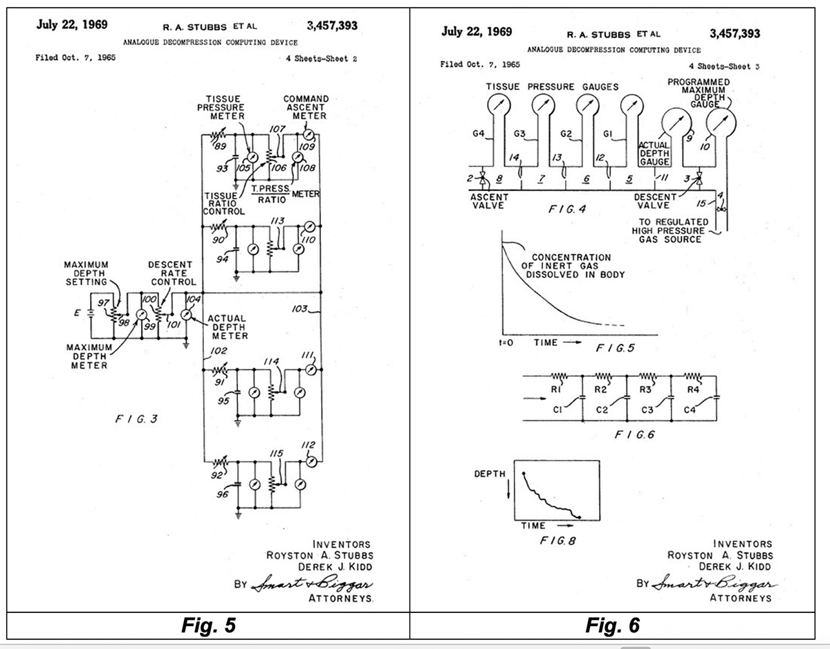 |
One of the problems with these analog electronic devices designed for real-time monitoring of decompression profiles was the extreme stability and precision required of some of their components. These, having to precisely represent the long time constants required by the various theoretical models employed, were consequently very expensive. In particular, the main problem with these components (primarily resistors and capacitors) was their high sensitivity to the circuit's operating temperature, which varied significantly during the device's operation. It was therefore necessary to compensate for these effects with additional circuits or other design solutions of questionable effectiveness. During Kidd and Stubbs's experiences, analog electronic computers usable directly during dives had never been designed and built. However, Stubbs carried out extensive research during the development of the PADC (the aforementioned Pneumatic Analogue Decompression Computer), using a generic electronic analog computer for processing and analyzing decompression models.
A dedicated electronic analog computer was also designed and built, primarily intended for the accelerated processing of decompression profiles with output visible on a digital display and XY plotter. The unit could also be used to analyze any type of diving profile. Most of these computers were used primarily for dive planning and analysis. These devices were capable of determining various diving parameters, such as total gas supply requirement, maximum no-decompression bottom times, and decompression stop depths and durations, even for complex dive profiles and repetitive dives.
As previously mentioned, the mechanical components and mechanisms of a PADC were sensitive to vibration and shock and could suffer from calibration loss or difficulty reading depth. Furthermore, mechanical readouts such as pressure gauges or chart recorders were unable to ensure high accuracy for deep dives down to 90 meters. In 1972, the DCIEM designed and built a series of pneumatic computers in which most of the mechanical components were replaced with electronic ones, using pressure transducers in place of Bourdon tubes and electronic digital displays to read current depths and safe ascent depths. Instead of using complicated mechanical linkages, an electronic comparator and operational amplifiers were used to compare the pressures in the four tissue compartments and to select and calculate the safe ascent depth. These devices were hybrids that employed both pneumatic and electronic technology and were therefore called analog pneumatic-electronic diving computers.
In the early 1970s, the development of microprocessors made it possible to design and build small, portable computers dedicated to monitoring both real dives or simulated hyperbaric chamber dives and calculating decompression profiles. Most of these models were designed exclusively as desktop instruments and were widely used to manage scientific and military umbilical dives or to study and test advanced decompression models in hyperbaric chambers.
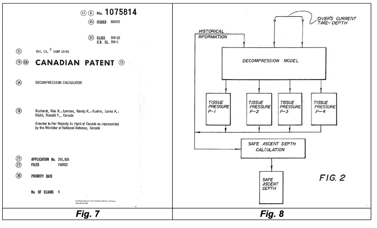
The DCIEM started a program to develop a series of microprocessor-based computers (Nishi, 1978) through collaboration with the Canadian company CTF Systems, Inc., of Port Coquitlam, British Columbia. The first computer, the desktop model XDC-1, completed in 1975, was a real-time dive computer/monitor (Lomnes, 1975) into which information could be entered from a keyboard to generate or analyze dive profiles. In real-time mode, the computer could be programmed to acquire readings from a pressure transducer carried by the operator while underwater and connected to the ground via an umbilical (or installed inside a hyperbaric chamber), and then calculate and display the safe ascent depth (the minimum depth to which one could ascend without having to perform a safety stop) for online diving control. The patent for this device, published in Canada on April 15, 1980 with number 107814, clearly referred to the use of the four-tissue compartment decompression model developed by Kidd and Stubbs (see Fig. 7 and Fig. 8).
 |
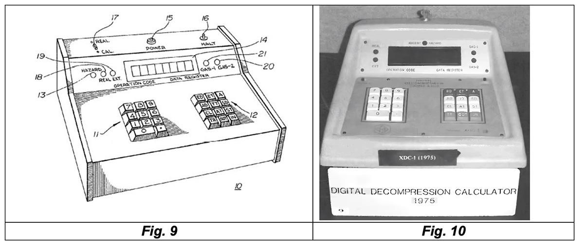
The unit was fed by a permanent power source, so as not to lose the dive data stored in its memory. It could thus easily handle even long, repetitive dives. The computer included a large digital display showing bottom time, actual depth, and safe ascent depth. A fourth display showed the ascent rate or the remaining no-decompression time and total ascent time (see Fig. 9 and Fig. 10).
 |
The only component of this system that required calibration was the pressure transducer, carried by the diver or placed inside the hyperbaric chamber.
The next panel type model, the XDC-2 (see Fig. 11 and Fig. 12), was programmed like the XDC-1 with the 1971 Kidd-Stubbs four-tissue compartment decompression model and could thus replace both the Mark VI S PADC model and hybrid pneumatic-electronic analog computers.
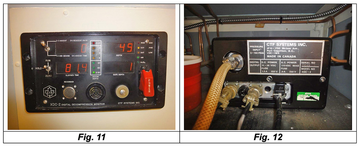 |
Approximately 30 units of this model were built, several of which were sold to other agencies for the management of hyperbaric chambers. The XDC-2 remained in use at the DCIEM for over twenty years. In 1983, the decompression model used by this device was replaced by the more advanced DCIEM 1983.
A third model, designed for underwater application only and completed in 1978, was the XDC-3 computer, for use in real dives up to 60 meters deep (see Fig. 13).
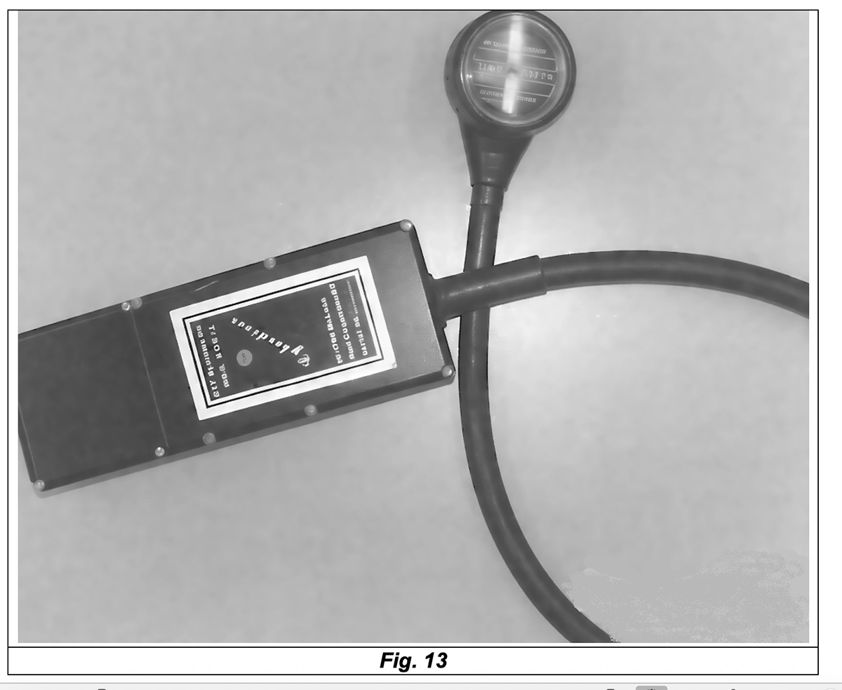 |
This model consisted of a watertight main body containing the electronic circuit, the pressure sensor, and the batteries, and of a round LED display connected to the computer body via a flexible, pressure-resistant hose. The electrical wires connecting the main circuit to the display were installed inside this hose. The body of the device was typically mounted on the back of the tanks, while the display was attached to one of the diver's sides (in the same position as a traditional pressure gauge) in a location where it could be easily reached and red.
One of the major problems that arose during the development of the XDC model series was that the technology at the time was not capable to fully meet the dive computers design needs. Miniature pressure transducers were very expensive, so CTF had to design its own transducer for the purpose. Although the XDC-3 used a CMOS (Complementary Metal-Oxide-Semiconductor) microprocessor, the Intersil IM6100, CMOS memory chips were not available, and the device consumed a significant amount of power. The light-emitting diode display, which showed bottom time, current depth, the minimum depth to which it was possible to ascend without making safety stops, the remaining no-deco time, and the total ascent time, was controlled by an inertial switch that turned the display on for six seconds when required. With four 9-volt alkaline batteries, the operating time was only 4 hours (with an average power consumption of about 5 W, equivalent to that of a small incandescent light bulb), making the computer very expensive to use.
Although the batteries could be replaced one at a time, without interrupting the instrument's power supply and thus losing the dive data stored in the memory, managing repetitive dive programs over long periods of time became very burdensome. In some cases, it was possible to use various energy-saving measures, such as the one adopted in the computer for the United States Navy developed by Jennings (1977) and patented under US patent number 4,005,282 (see Fig. 14 and Fig. 15).
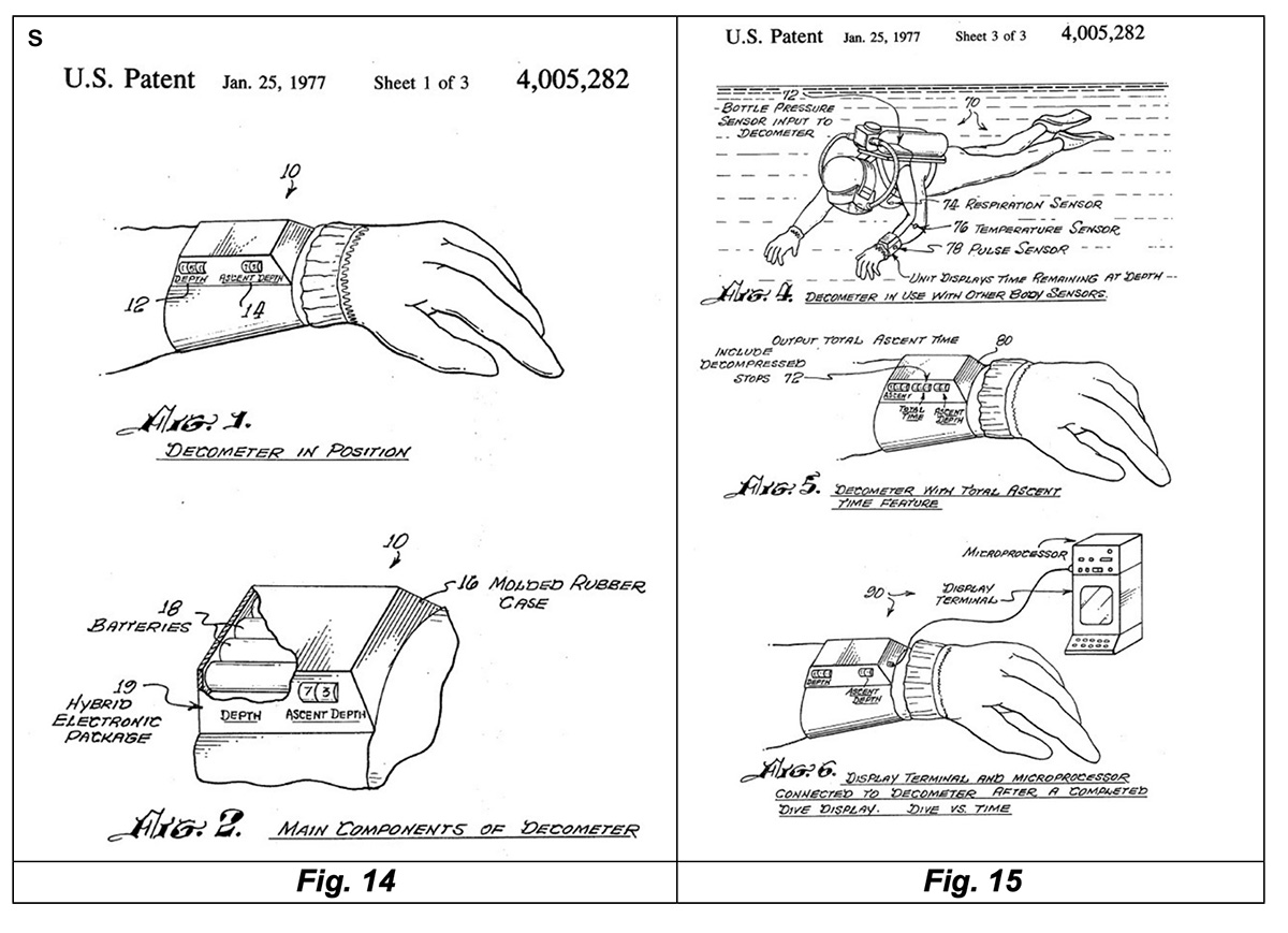 |
According to the U.S. Navy's specifications, this computer was supposed to have highly innovative performance and functionality including a sensor to measure heart rate, a temperature sensor placed in contact with the diver's skin, a sensor to measure breathing rate, and a decompression model capable of taking all these parameters into account. In reality, probably because of the complexity of the project and the unavailability of the technology at that time to support the various desired technical solutions, this device does not appear to have ever progressed beyond the initial study and testing phase. Some of the features requested by the Navy would only materialize in the computers developed several decades later. One of the energy-saving measures used in this military computer, although a low-power demanding Intel 8080 microprocessor was already used, was to have an operating algorithm capable of automatically shutting down the computer between calculations.
Using lithium oxide batteries instead of alkaline ones, the XDC-3's operating time was estimated to be 16 hours. Considering the cost of these batteries in 1977, this computer was indeed very expensive to operate in this configuration. Given these obvious operational limitations, only five prototypes of the XDC-3 computer were built.
The fourth phase of the DCIEM research program on microprocessor-based digital dive computers was aimed at designing an electronic system specifically dedicated to calculating and managing decompression (Retallack et al., 1977). This new phase was intended to lead to the development of a new model, the XDC-4, also conceived as a desktop computer for managing umbilical dives or simulated dives in hyperbaric chambers. The XDC-4 project also included the development of a single dive control language capable of managing any mathematical approach to decompression, for both real and simulated dives. A second objective was to extend the functions of the previous XDC-2 model to include the management of dives with breathing gases other than air. The instrument was equipped with two microprocessor-based modules. These modules operated simultaneously but separately, one for monitoring and managing real dives (with umbilicals) or in hyperbaric chambers, and the other for preparing dive tables, analyzing dive data, or experimentally developing decompression models. The XDC-4 version was conceived and designed in the late 1970s, just before desktop personal computers became available on the market.
Due to delays in the hardware and software development of this new model and the rapid proliferation of personal computers, the XDC-4 became obsolete before it was even completed. Most of the intended functions could now be implemented on a desktop personal computer at a fraction of the development costs of the XDC-4. Therefore, the decision made by the DCIEM regarding the management of experimental and other hyperbaric chamber dives was to use personal computers going forward. The XDC-4 project was therefore shut-down. A PC/XT compatible desktop personal computer (XT stood for eXtended Technology and was an early IBM PC model), equipped with hardware and software for data acquisition from pressure sensors, was then programmed with the DCIEM 1983 decompression model and another experimental model based on helium-oxygen breathing mixtures. This PC was then used for real-time dive management. The primary advantage of using a PC was the flexibility available for programming and managing subsequent corrections and modifications. It was also possible to use various higher-level languages for model programming and real-time data acquisition. Thanks to color monitors, the output dive information could be displayed in various ways, using color graphs or tables. This information could also be stored on hard drives for later analysis
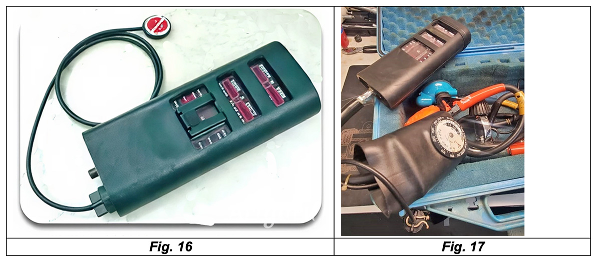
The Cyberdiver computer, a true dive computer designed for real underwater diving, was an attempt to apply the results of research conducted for the DCIEM to the recreational diving equipment market. Kybertec International Inc. was founded by two of the managers of CTF Systems, Inc. in 1978 to market a dive computer derived from the XDC-3. The first model, released in 1978-1979, was based on the U.S. Navy tables and consisted primarily of reading and interpolating these tables, stored in the device, as a function of maximum depth and bottom time (see Fig. 16 and Fig. 17).
 |
Compared to the experimental XDC-3 model, this device was substantially different in terms of construction and included the following design elements:
- The body was made of transparent polycarbonate and allowed the display information to be viewed. This consisted of arrays of red light-emitting diodes (the technology available at the time) and was an integral part of the electronic board on which the microprocessor and other circuit components were mounted.
- The polycarbonate body was installed inside a thick, highly resistant rubber sheath that protected the device from impacts and accidental contact. Several openings in this outer rubber shell allowed the device's displays to be viewed.
- A pressure sensor was added to measure tank pressure, with a related pneumatic adapter for the high-pressure hose linked to the regulator's first stage. This characteristic would later become a standard feature on air integrated models that would appear on the market several years later. The four 9V batteries had been replaced with a single 9V alkaline battery.
- The cylindrical cap of the battery compartment also worked as an on/off switch through a rotation of about 90 degrees.
- An external battery pack was provided to allow the device to have adequate working time. The connection to this external pack was made through the battery compartment cap and used an external pressure-resistant cable. The external battery pack could be supplied in various configurations such as that shown in Fig. 16 (probably a watertight circular box containing lithium oxide batteries) or that shown in Fig. 17, a solution with an external rubber protective sheath and almost certainly consisting of a 9V alkaline battery pack. This element was fundamental for the functioning of the computer because, in the event that the power supply to the device was interrupted, all the parameters and fixed constants used by the software to operate would be lost because they were stored in a RAM (Random Access Memory, which is volatile and loses data when the computer is turned off) and not in ROM (Read Only Memory, which retains the stored information even after the device is turned off and then restarted).
The next model, the Cyberdiver "SKANA," was a modern dive computer based on the 1971 Kidd-Stubbs four-tissue decompression model. It was a true real-time decompression calculator capable of accounting for the actual depth of the dive and any type of profile (square and multilevel dives). Approximately 700 units of both Cyberdiver models were sold. Unlike the first version of the Cyberdiver, based on US Navy tables, in which all calibration parameters were loaded into CMOS RAM (and therefore required a complete reset of the instrument after battery depletion), the Kidd-Stubbs (SKANA) version did not require parameters to be stored in RAM and thus reached greater popularity and longer use.
I recently found and acquired a model of this latest model (the SKANA), which allowed me to analyze the various construction elements in greater detail and identify the updates made compared to the previously described model. The results of this analysis are described below: - From the design point of view this model is very similar to the previous unit as shown in Fig. 18 and Fig. 19.
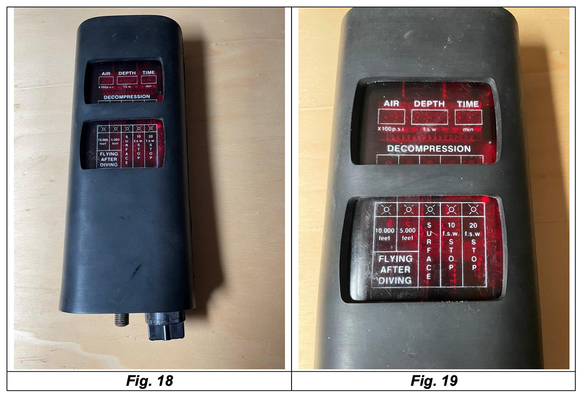 |
The computer display layout has been revised, with the red LED display now located at the top. This display indicates the residual pressure in the tanks (on the left side), the current dive depth (in the center), and the elapsed diving time (on the right side). The array of five red LEDs under the word "DECOMPRESSION" is used to manage the ascent phase, including any decompression stops, and the waiting time required for flights or altitude climbing. The lower window is simply a table that allows you to understand the meaning of the information displayed in the row of LEDs under the word "DECOMPRESSION." The first two LEDs on the left, when lit, indicate that it is not possible to ascend to an altitude higher than 10,000 feet (about 3,000 meters) or 5,000 feet (about 1,500 meters), respectively. The central LED, if lit, indicates that you can ascend to the surface while the two LEDs on the right, also if lit, warn the diver that it is necessary to make a decompression stop at 10 feet (3 meters) or 20 feet (6 meters).
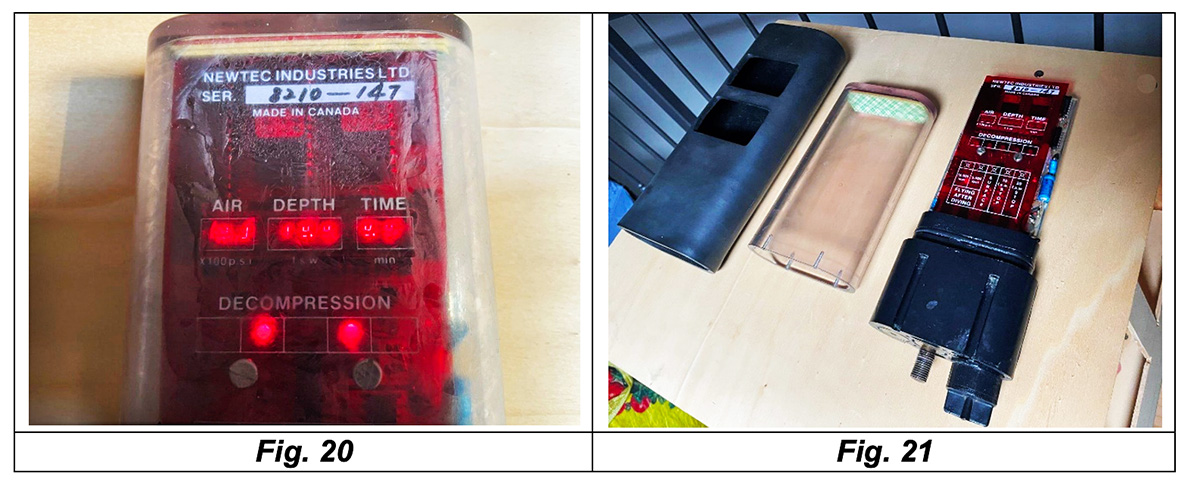
- Surprisingly, the device started working after installing a new 9V alkaline battery, more than forty years after its manufacturing date (see Fig. 20). However, the layer of silt that had deposited on the internal walls of the polycarbonate body (perhaps the residue of the computer being flooded during a dive in a river or lake) suggested the need to proceed with disassembly and cleaning the device. After disassembly, the three main components of the instrument (the electronic board including the display, the pressure sensors and the battery compartment, the external polycarbonate body and the protective rubber sheath) are shown in Fig. 21.
-
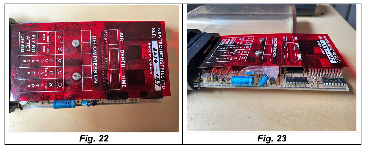
- A transparent red plastic sheet is mounted over the computer's electronic board and includes all the text necessary to understand the visual and numerical information displayed by the light-emitting diodes and LEDs located under the sheet and integral with the electronic board (see Fig. 22). The side view of the electronic board (see Fig. 23) allowed us to identify all its main components, including the aforementioned inertial switch. This consists of a simple glass ampoule containing mercury that opens or closes electrical contacts depending on the position of the computer.
 |
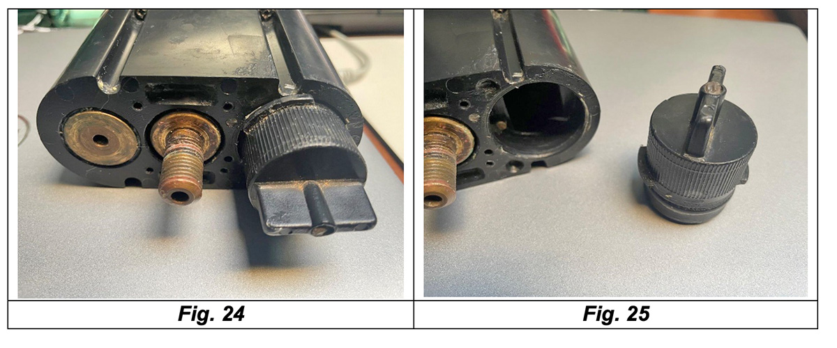
- The analysis of the lower part of the computer body allows us to appreciate the other main elements of the device in greater detail (see Fig. 24). On the left side, you can see the hole that connects the external environment to the depth sensor (pressure sensor). In the central part, the threaded adapter for high-pressure connection to the regulator is installed to read the tanks residual pressure via a second pressure sensor. The right part is dedicated to the compartment for the replaceable internal 9 V battery and its cap, which also works as an on/off switch (see Fig. 25). Unlike the previous model and as mentioned above, the cap no longer receives power from the external battery pack, although it is assumed that the external power supply system could still be compatible with this updated version of the computer.
-
-
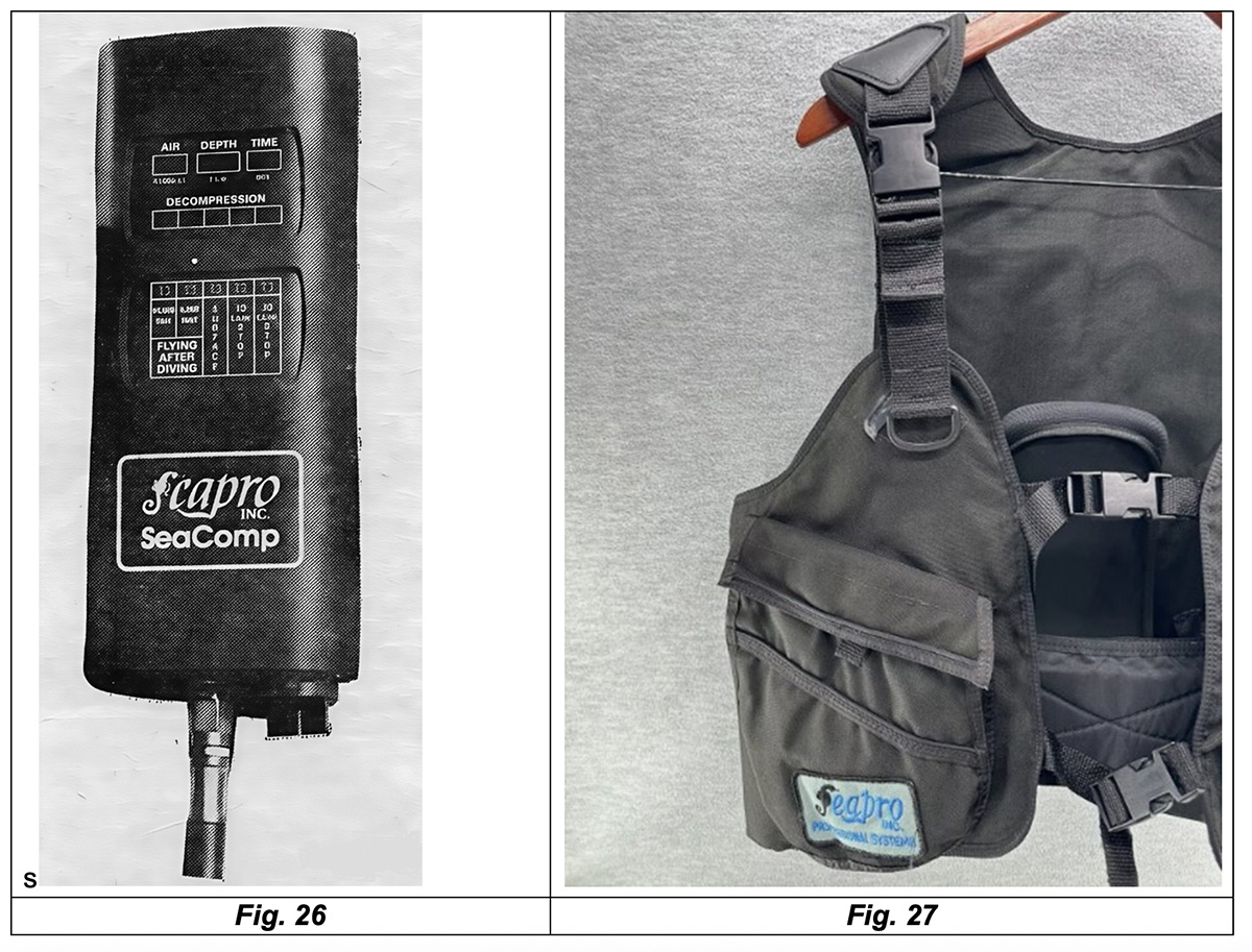
Outside of the Canadian market, I found only one example of distribution of this version of the computer in the USA through Seapro Inc., which marketed the computer through the SeaComp name (see Fig. 26). Despite extensive online research on this US company, which likely operated on the market during the 1980s and 1990s, very little information was found, despite Seapro Inc. being active in the sale of various equipment intended for sports diving, including some BCD models (see Fig. 27).
-
-
The Cyberdiver, primarily in its improved "SKANA" version, was an innovative computer with many interesting features. However, it was unsuccessful for several reasons. Kybertec was a small company, and one of its main problems was the lack of funding to address the various software bugs and market the computer effectively. Technically, there were also some issues. The designers, although experienced in electronics and microprocessor applications, were not sufficiently experienced in underwater packaging, and water flooding into the polycarbonate body was one of its main flaws, as evidenced by the condition of my previously analyzed unit. The depth sensor was based on a design resulting from a DCIEM research contract with CTF and was essentially a digital transducer.
There were no real problems with the transducer, except that it could fail due to the aforementioned water ingress. Due to a lack of funding, the company was never able to begin Phase 2 of the redesign, which would have improved the sealing of the external casing to eliminate flooding. The other major problem with the Cyberdiver was that the designers were too far ahead of their time; the technology wasn't yet ready for what they wanted to achieve at an affordable price. The Cyberdiver was relatively expensive, and the end-user market wasn't ready yet. Kybertec didn't apply for a patent for this computer, as it would have been too expensive.
In theory, patents should have been applied for at least in Canada, the United States, the United Kingdom, and Japan. DCIEM's experience patenting devices developed under CTF contracts, particularly the XDC-1, raised some difficulties in the application process. The patent was granted in Canada (Burbank et al., 1980), but was rejected in the United States because, according to the U.S. patent examiner, the previously cited U.S. Navy patent (Jennings, 1977) had prior claims on almost everything claimed to be novel for the XDC-1. With that experience, it would have been very difficult to obtain a patent for a dive computer that was more similar to the Jennings computer than the XDC-1. Kybertec also considered filing a patent and suing potential infringers but decided that there was no basis for pursuing this course of action.
In 1981, the rights to the technology and design of this device were sold to Newtec Industries Ltd. of Burnaby, British Columbia, the company that had also manufactured the previously analyzed model (see Fig. 22). However, this company decided not to develop this model further because it believed the market was not large enough to justify further investment. Consequently, the Cyberdiver was discontinued, probably at the end of 1982.
And so, ironically, this computer was discontinued just as the era of digital dive computers for sports diving was dawning, with the first successful models including the "Deco Brain Hans Hass" by Divetronic (1982) and "The Edge" by Orca Industries Inc. (1983).__________