In the immediate post-war years in the United States but also in several other parts of the world, including Italy, the great desire to discover the wonderful underwater world by going beyond the narrow limits allowed by freediving, induced many enthusiasts with a spirit of initiative and artisan skills, but often with little money in their pockets, to invent and manufacture their own air breathing apparatus directly in their home garage.
In Italy, for example, some had managed to find military ARO (oxygen rebreather) units cheaply and used them without knowing how to use them, often ending up being victims of their ignorance, with numerous accidents with often fatal outcomes. In the USA, however, "little inventors" were very widespread in those years during which the industry was slowly reconverting from predominantly military production towards the needs of a rapidly expanding civilian market. The average American user had to deal with the scarcity of specific products for sport and leisure and also with family finances that the war had often made minimal. For diving enthusiasts, the most desired object at the beginning of the 1950s was undoubtedly the Aqua-Lung, the first true self-contained breathing apparatus (SCUBA unit) invented by the Cousteau-Gagnan duo and which arrived in the United States at the end of 1948 to be then distributed through the U.S. Divers owned by René Bussoz.
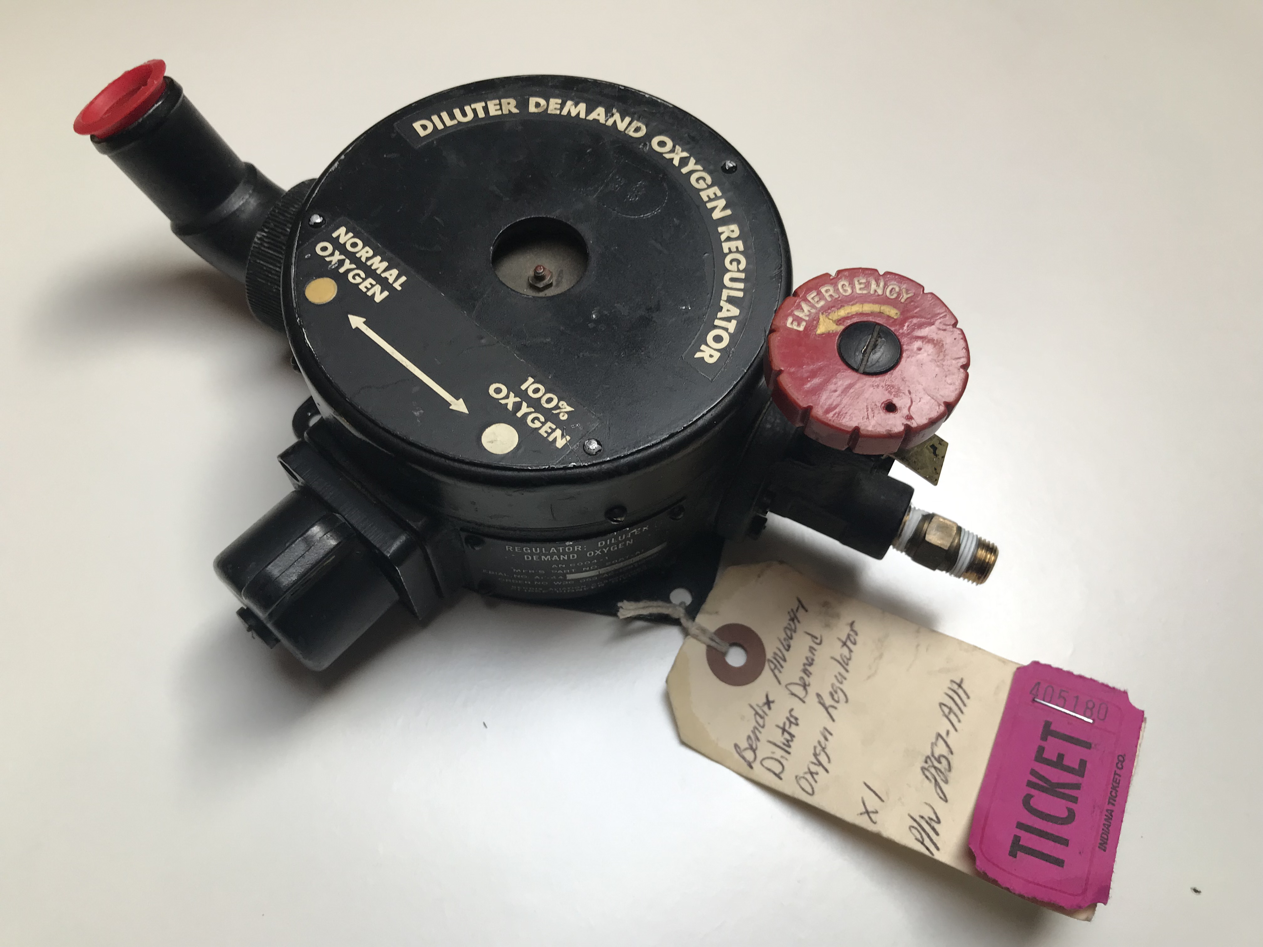
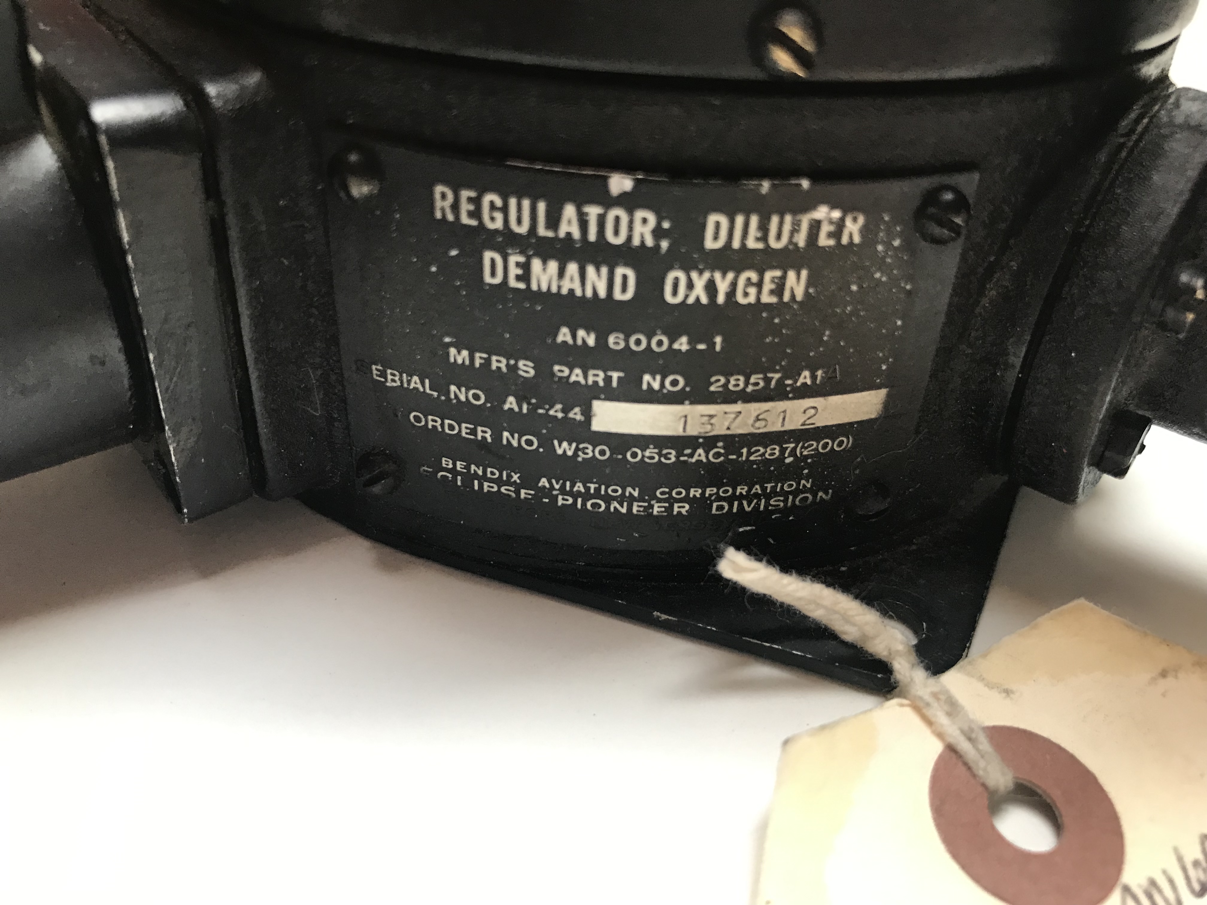
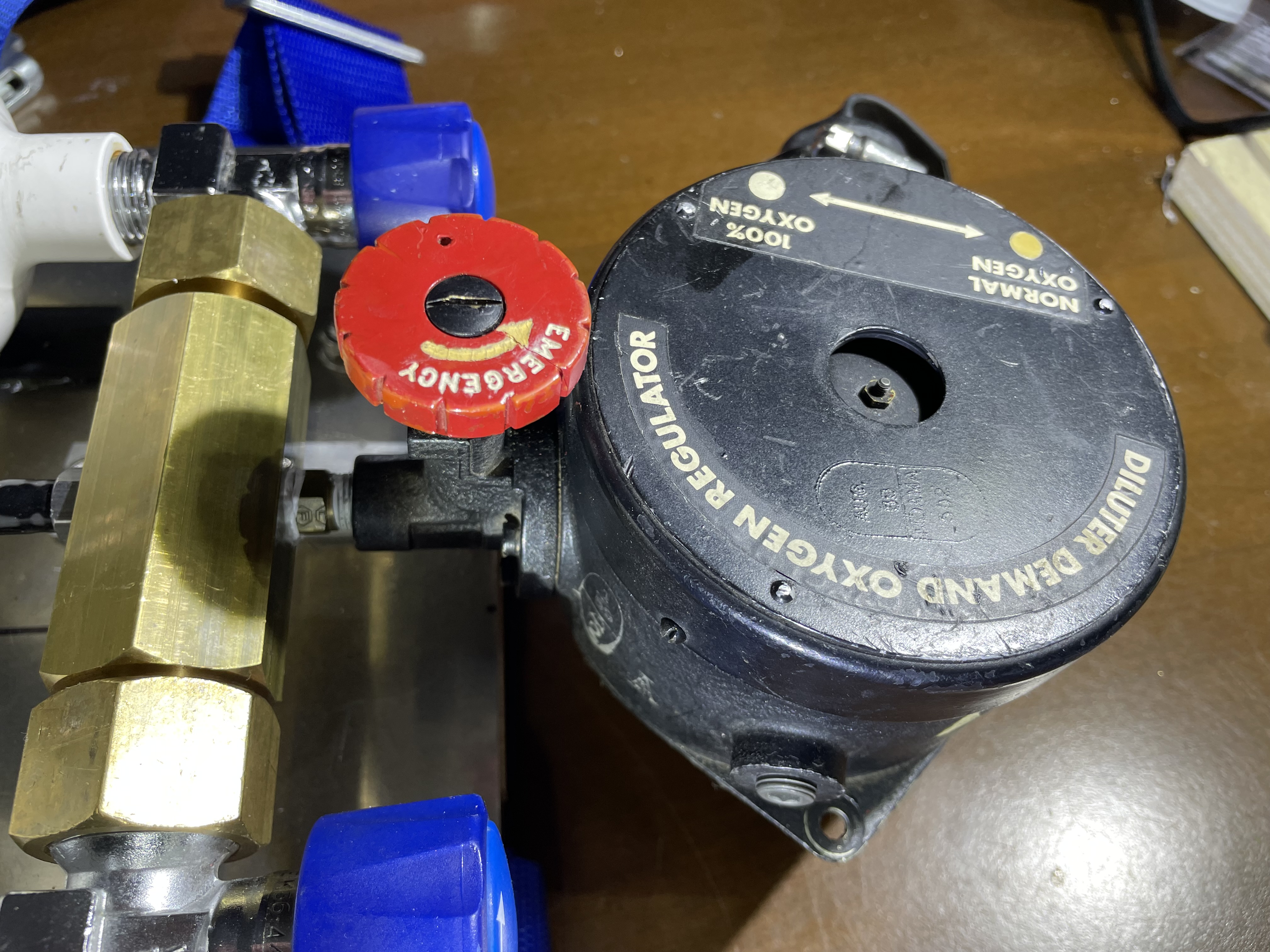
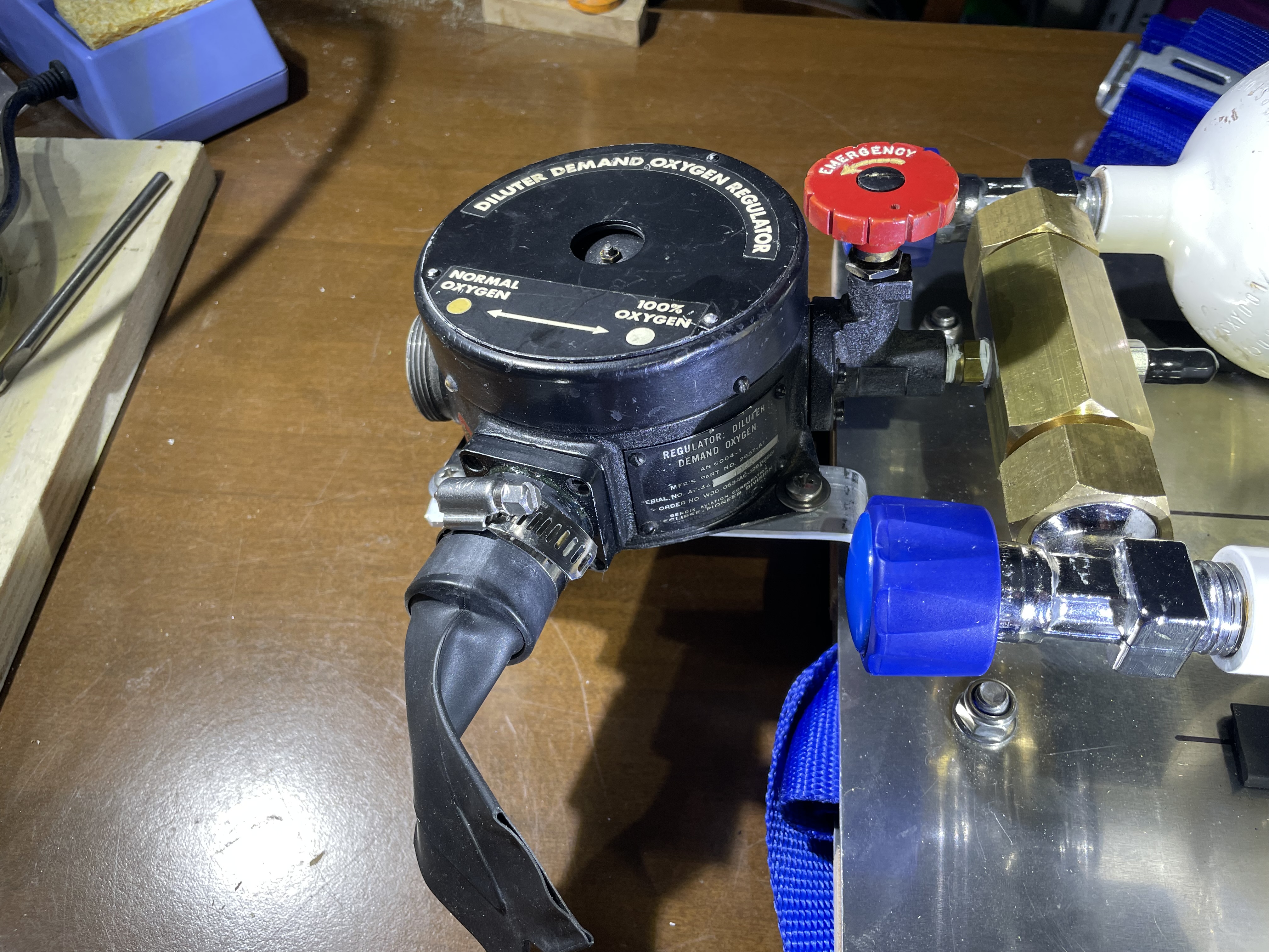
The units available were still few compared to the demand but, above all, their price (around 160 dollars for the basic version) was well beyond the reach of most divers' budgets of the time. What to do then? Fortunately, even in this case there was no shortage of surplus military materials, suitable for use and modification for this purpose. The "heart" of what would become the most widespread home-built SCUBA unit in the USA from the immediate post-war period until the mid-1950s was the demand oxygen diluter regulator, identified by the code AN-6004-1, used in the air-oxygen breathing systems of military aircraft of the Second World War and produced by some specialized manufacturers (see figs. 1 and 2).
 |
 |
| Fig. 1 |
Fig. 2 |
The diluter regulator was of the demand type and was activated by a diaphragm mechanically linked to a valve which was in connection with a small oxygen tank (with a capacity of around 2 liters). Some specific knobs integrated into the regulator allowed the percentage of air, which was sucked in from the aircraft cabin internal environment, and oxygen to be supplied to the operators in a mix to be adjusted according to needs (e.g. flight altitude and severity of the flight maneuvers). Even the small tanks used for these applications could be recovered and used to manufacture these first rudimentary air breathing apparatus. We remember that the SCUBA diving tanks of the sizes we know today were not available on the market at the time and would only have been produced and distributed in significant numbers starting from the second half of the 1950s precisely to satisfy the growing number of enthusiasts of this new sport.
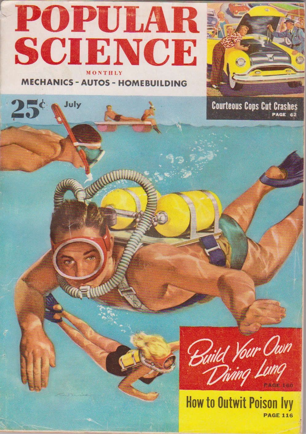
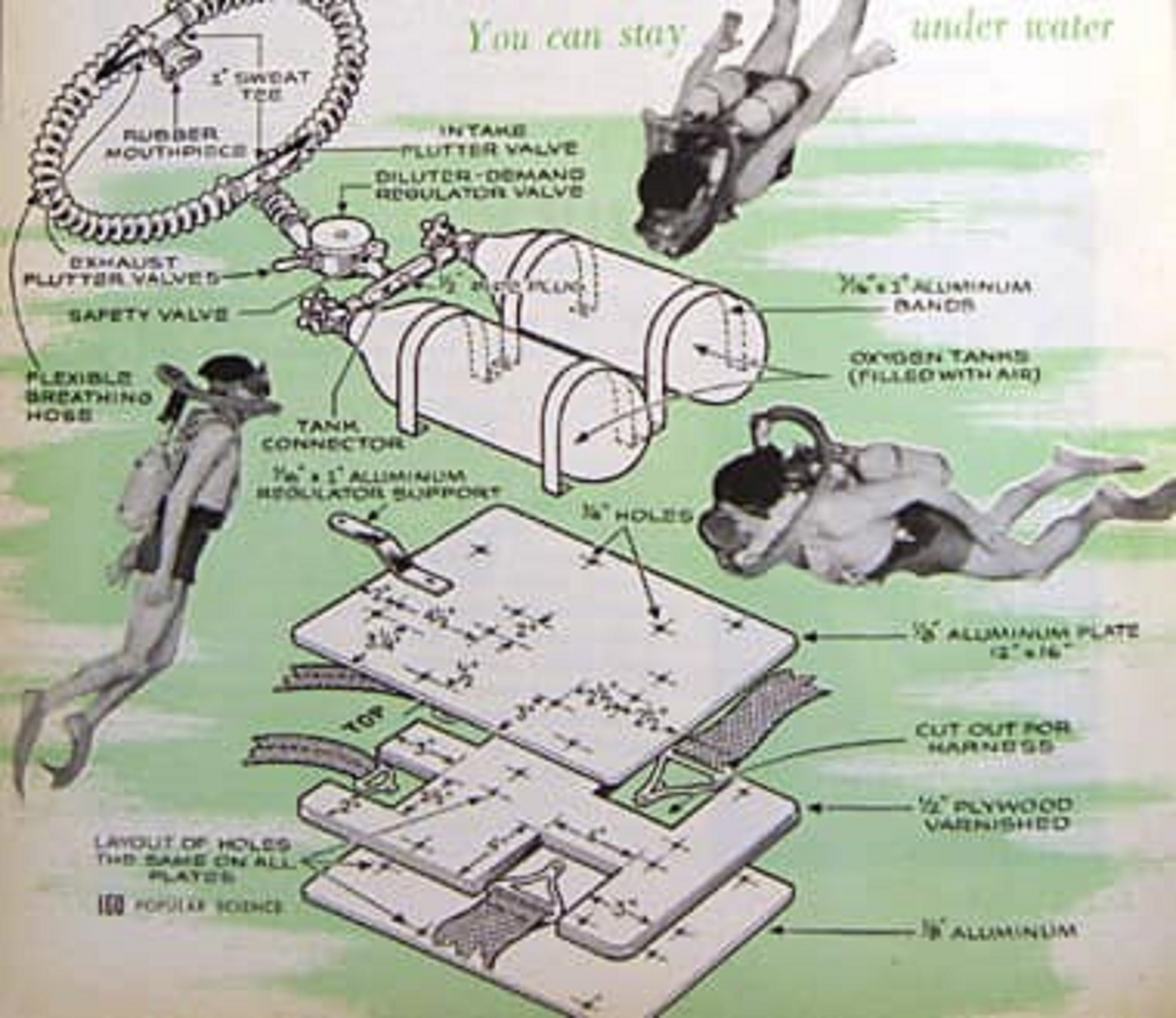
For a few decades, mainly to suggest solutions and construction techniques to the large audience of "do-it-yourself" enthusiasts, various publications had existed, including the monthly "Popular Science" magazine which, in the July 1953 issue, published the article “How to Build and Use a Diving Lung” (see figs. 3 and 4). The article, written by Herb Pfister, showed the entire process for self-building an air breathing apparatus at home using an AN-6004-1 military oxygen diluter and two small tanks originally used to contain carbon dioxide (probably used in some fire-fighting apparatus or for small inflatable boats) and with a maximum charging pressure of 1800 psi, approximately 124 bar. All the rest of the material described in the article could easily be found in the same military material warehouses or in emporiums that sold metal hardware and carpentry material (bolts, clamps, sheet metal, wooden panels, etc.).
 |
 |
| Fig. 3 |
Fig. 4 |
The author of the article claimed that the complete scuba unit (obviously excluding mask and fins) could have cost no more than 40 dollars, a value 4 times lower than that needed to purchase a real Aqua-Lung.
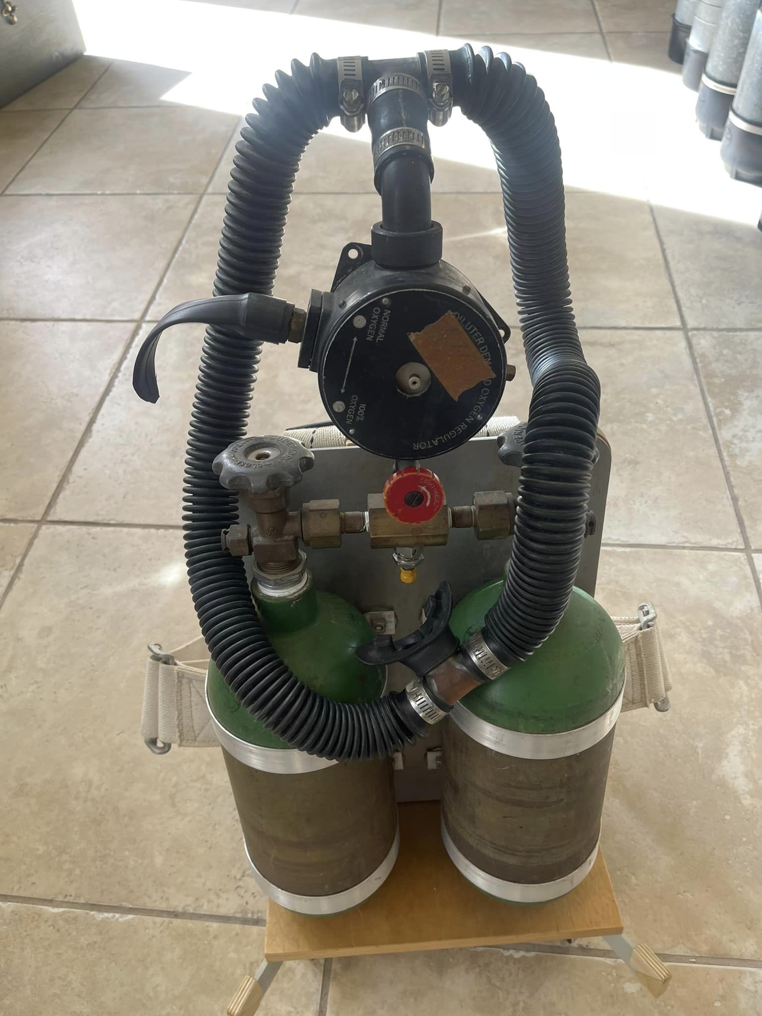
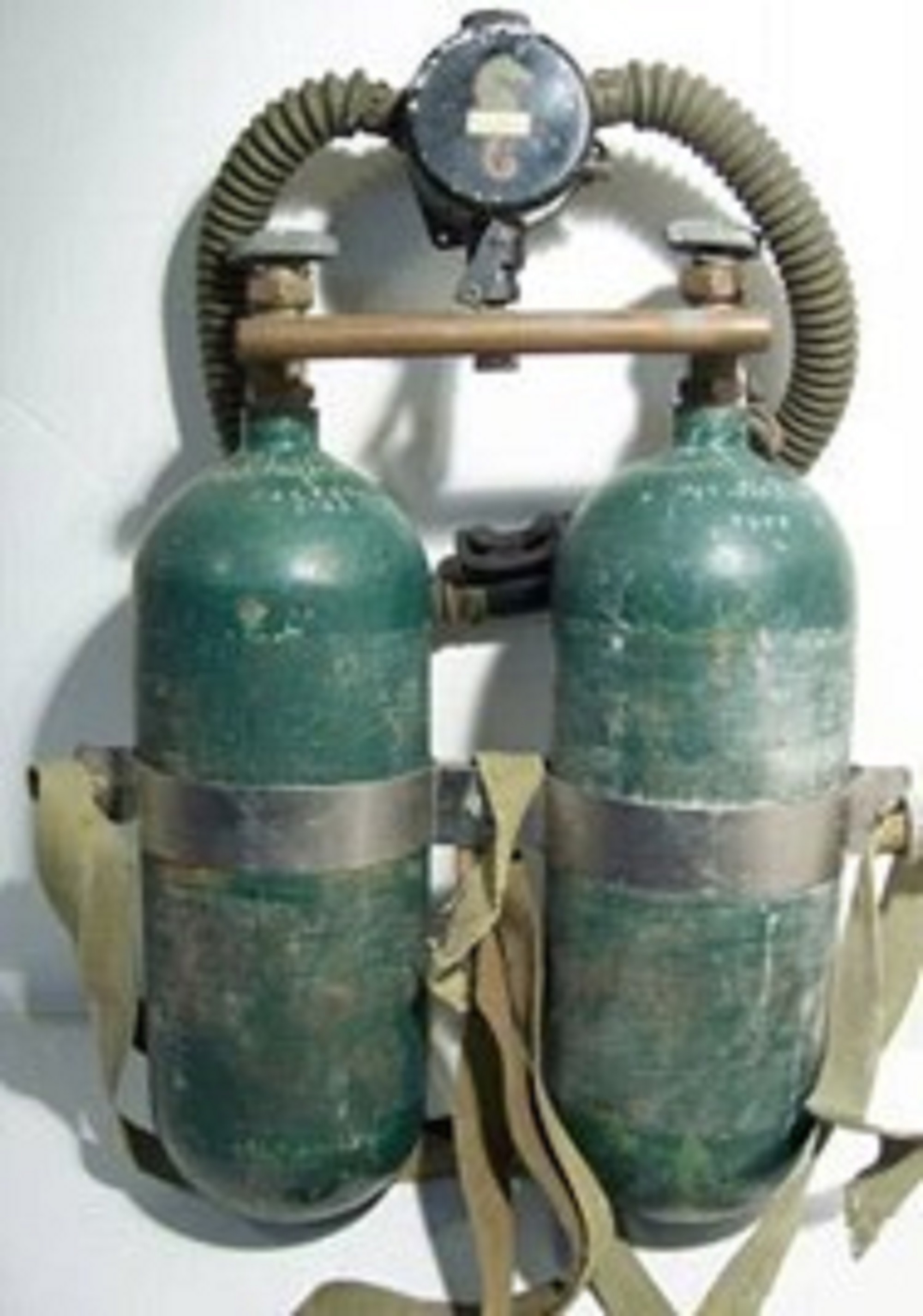
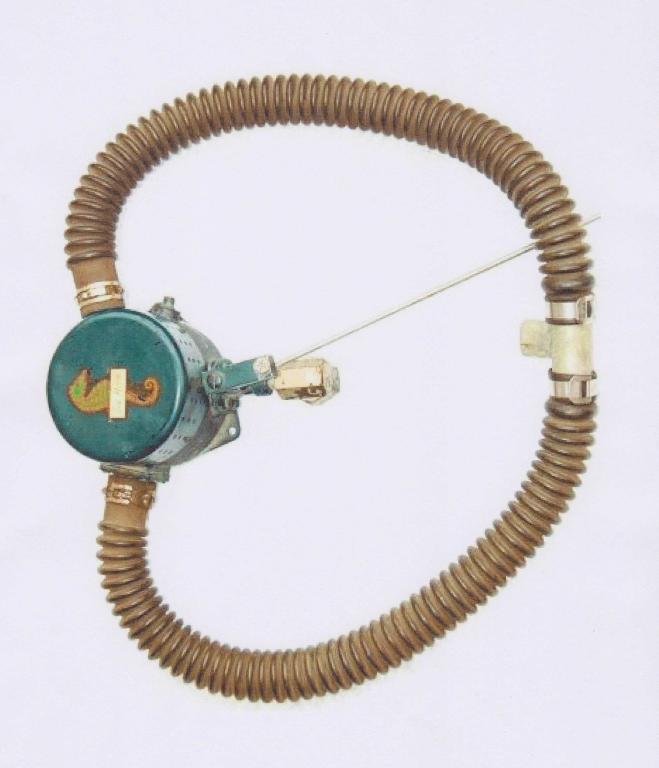
Two examples of this self-built breathing apparatus built in those years can be observed in figs. 5 and 6.
 |
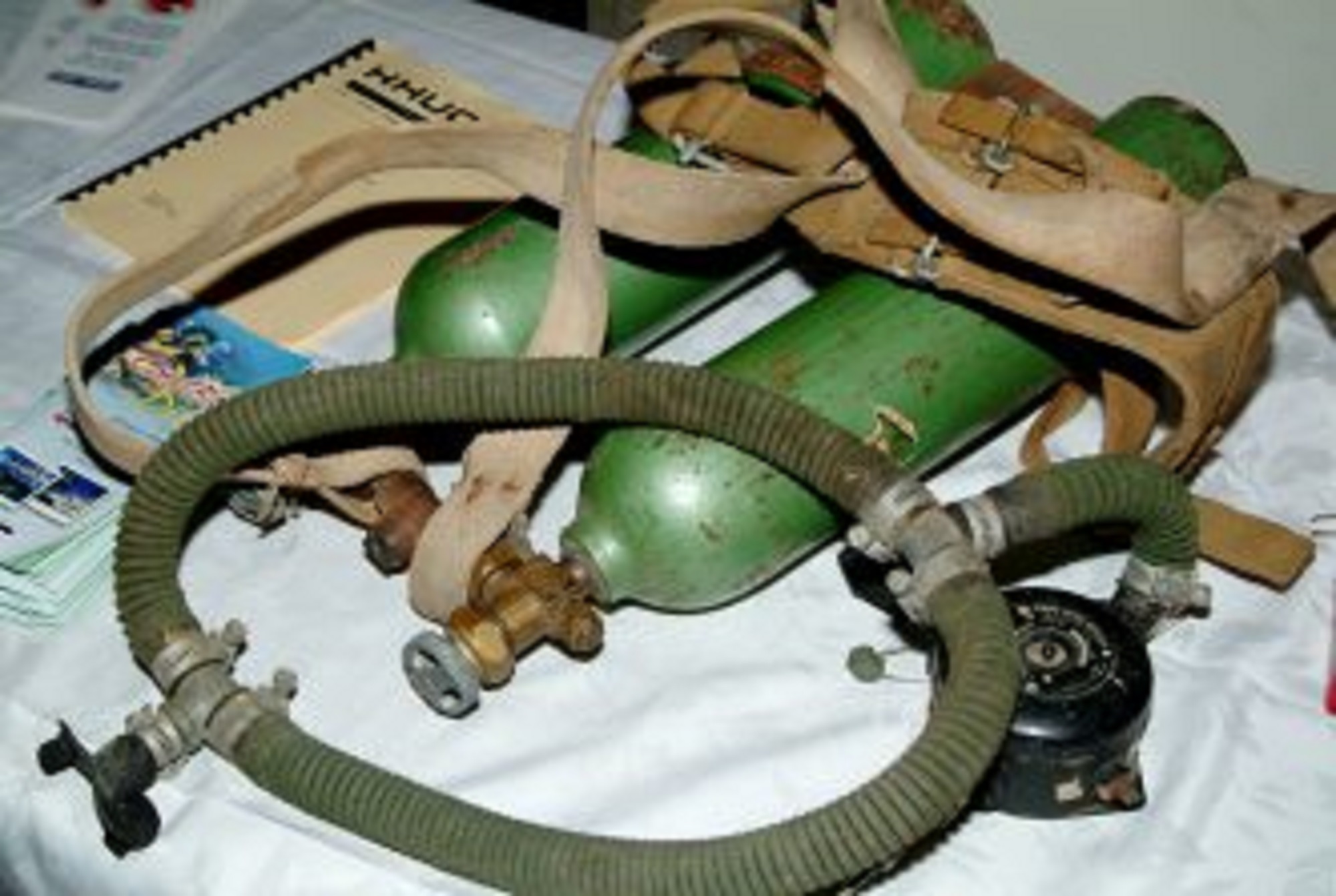 |
| Fig. 5 |
Fig. 6 |
Since I was lucky enough to find a copy of that magazine issue on one of the many online sites that sell old books and publications, I decided to try building myself this breathing apparatus by following the instructions in the Popular Science article as faithfully as possible. It will be a bit like going back about seventy years and experiencing the same joys and perhaps the same frustrations as our predecessors who, in order to satisfy their boundless desire to dive, were not afraid of facing challenges and difficulties of all kinds.
In particular, reading the original article and observing the technical solutions implemented, my main doubts were related to the real performances in terms of respiratory effort and air flow rates which could be offered by this device.
Of course, after about seventy years, it was completely unlikely or impossible to find exactly the same materials indicated in the article. For some components I therefore had to choose alternative solutions that did not substantially modify the functioning and performance of the original materials. These components were then assembled into the breathing apparatus in the same positions shown in the 1953 article. I also tried to follow as faithfully as possible the same construction and assembly sequences indicated in the magazine.
Tanks and connecting manifold
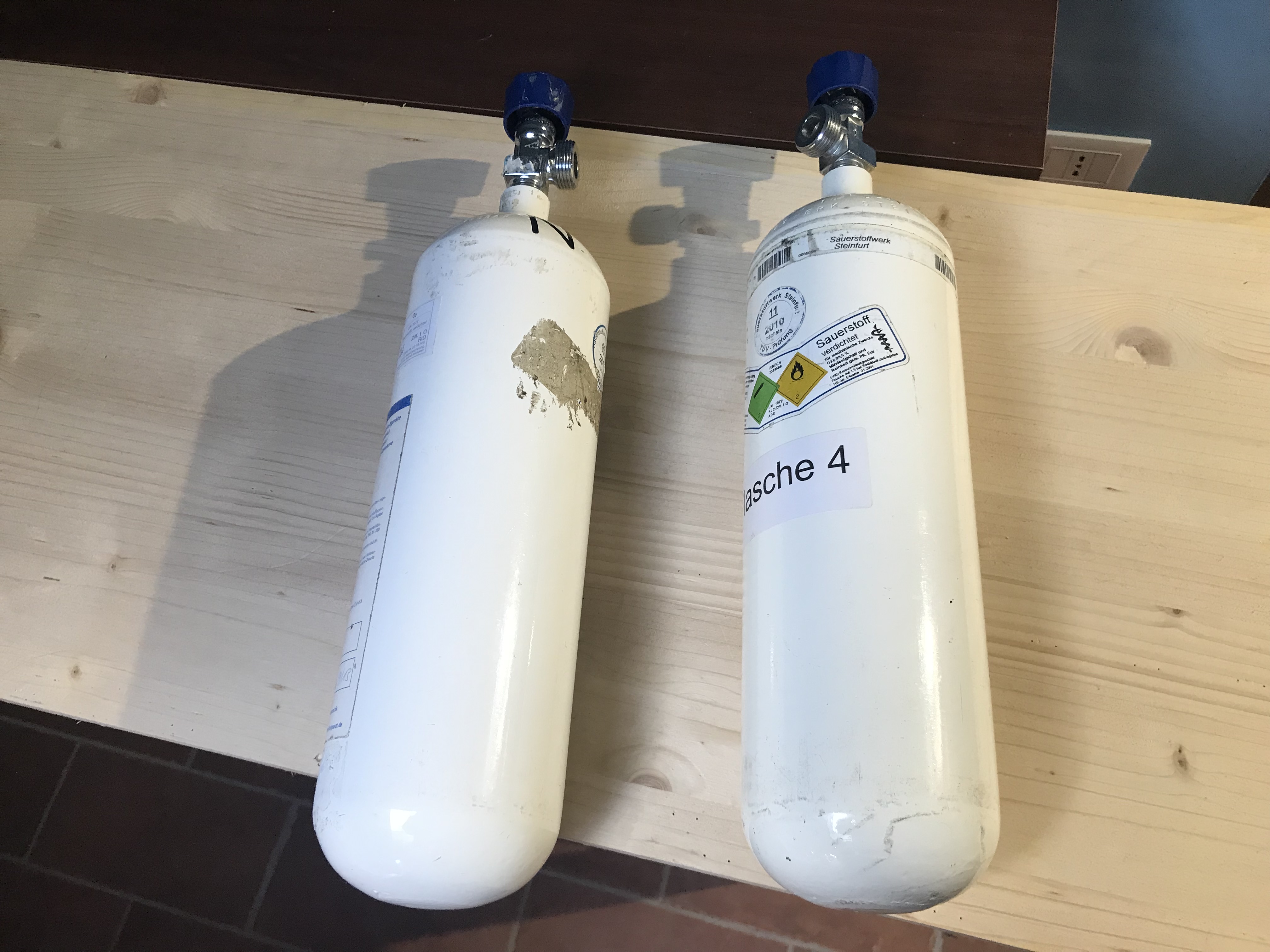
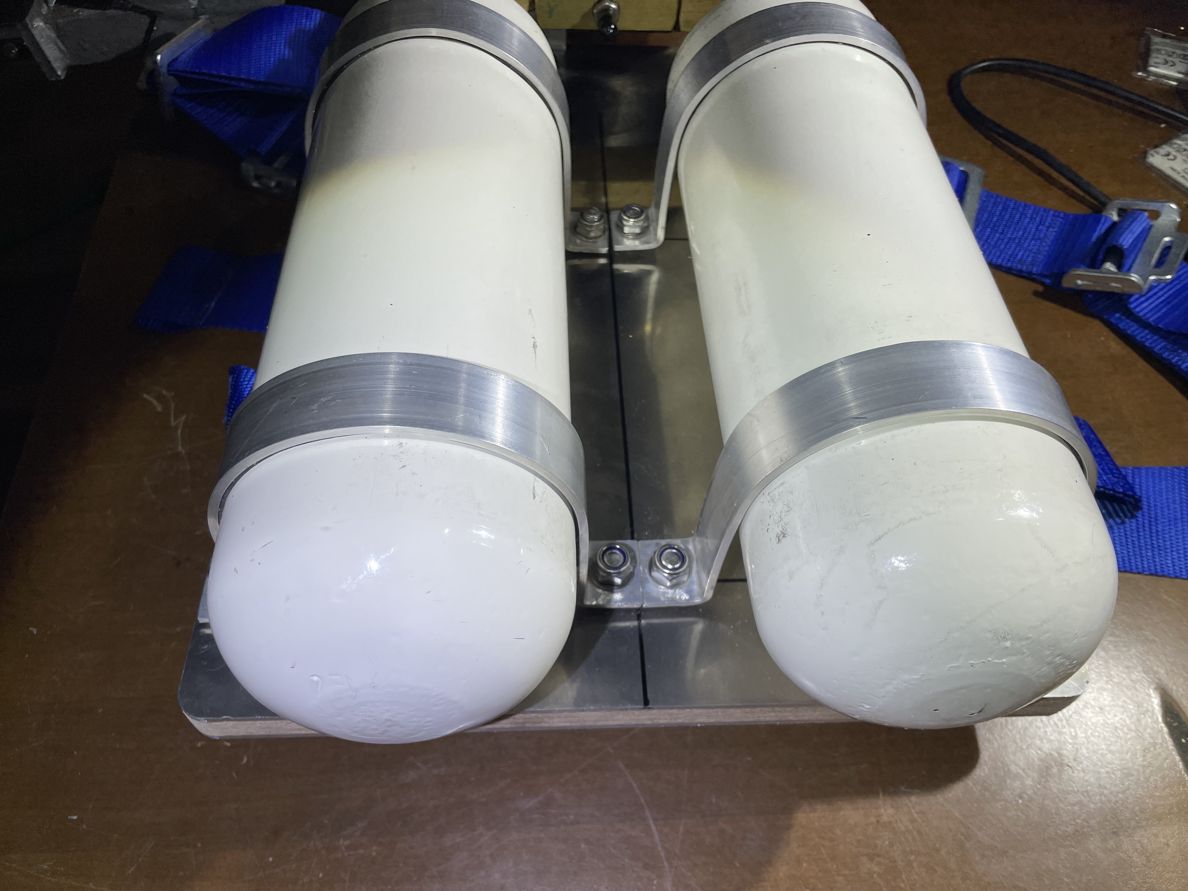
To remain aligned with the original scope of this work, namely that of building a self-contained underwater breathing apparatus using materials from other applications, I purposely decided not to choose tanks dedicated to underwater purposes which today are widely available in almost all the sizes. The choice fell on two 2-litre oxygen tanks used in medical applications (oxygen breathing systems for hospitals and ambulances). These tanks, which were found in Germany as used material at a very low price, are equipped with outlet valves with a 3/4" GAS male threaded connection which is the standard used in that country for these applications (see figs. 7 and 8). The tanks were provided with a hydrostatic test approval still valid.
 |
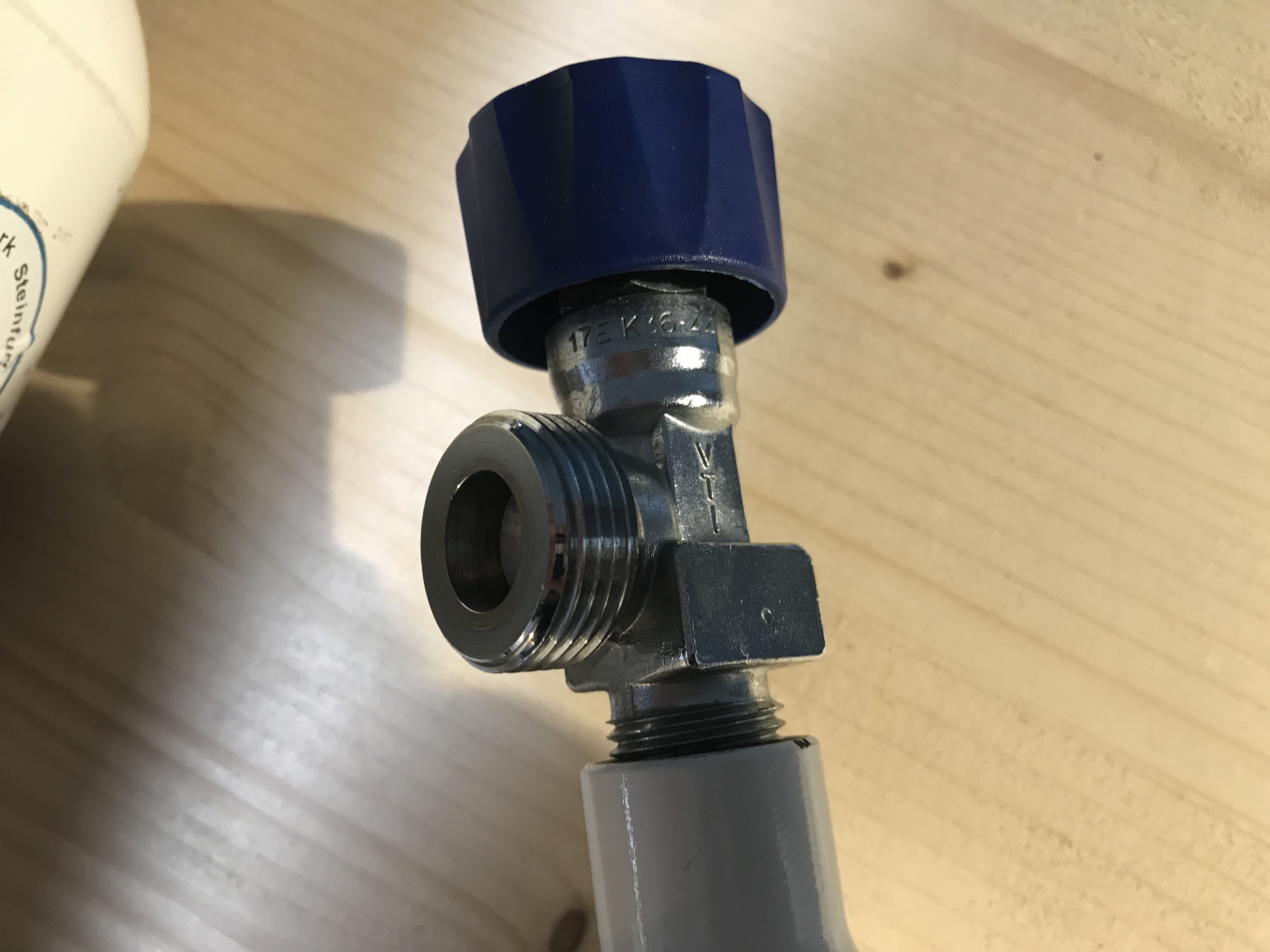 |
| Fig. 7 |
Fig. 8 |
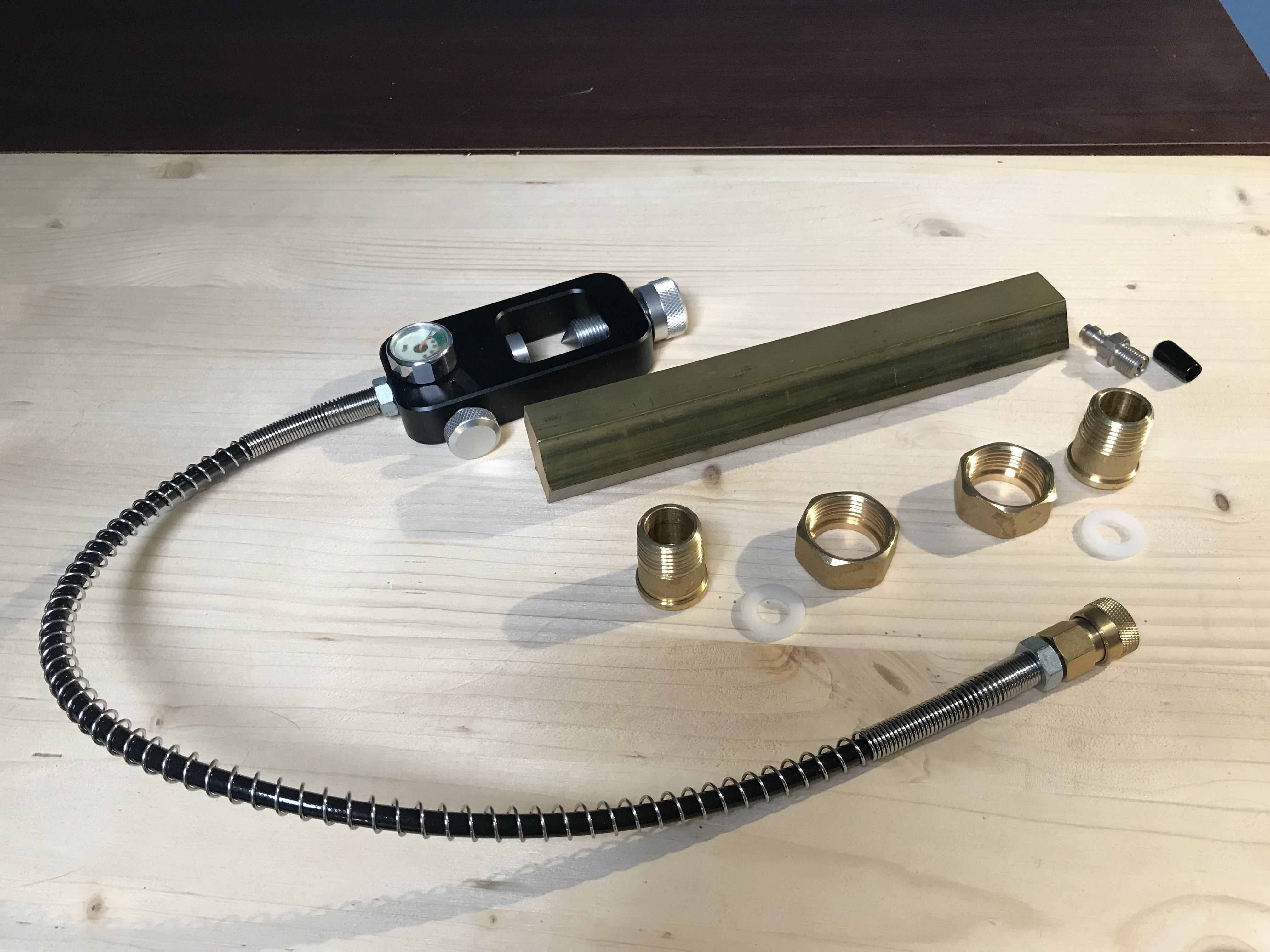
The materials and components selected for the building of the special connecting manifold and suitable for the tanks purchased for this application are shown in the figs. 9 and 10.
 |
 |
| Fig. 9 |
Fig. 10 |
The manifold will be obtained from a brass bar having a 36 mm hexagonal section, also purchased online. The bar will be cut to the right size, then machined and threaded to accommodate the various fittings for the tanks and the connections for the oxygen diluter and for the tanks charging valve. Considering that the tanks chosen for this work have medical oxygen outlet valves with 3/4" GAS male thread, the connection between the tanks outlet valves and the central manifold body will be ensured by the two special 3/4" GAS female - 1/2“ GAS male brass adapters also available on the Internet. The sealing between the adapters and the tanks outlet valves will be secured using nylon washers while the sealing between the adapters and the central manifold body will be achieved using a 1/2" GAS conical thread and Teflon tape. In the central part of the brass manifold, there will be a 1/8" GAS threaded seat for the connection with the oxygen diluter (directed upwards) and a 10x1 mm threaded seat for installing the one-way air charging valve (directed downwards). This valve can be linked a quick coupling connector which is part of the special charging equipment designed for receiving pressurized air from normal SCUBA tanks. This equipment is easily available on the Internet and is used for recharging toy weapons used in Paintball or the small tanks equipped with integrated regulators designed for short time dives at limited depths. The addition of this charging valve used in Paintball equipment was decided to make it easier the recharging of the breathing apparatus tanks, a task which, in the original solution, required the removal of the two tanks from the support plate first and then the recharge from a high pressure air compressor or from air pressurized larger tanks.
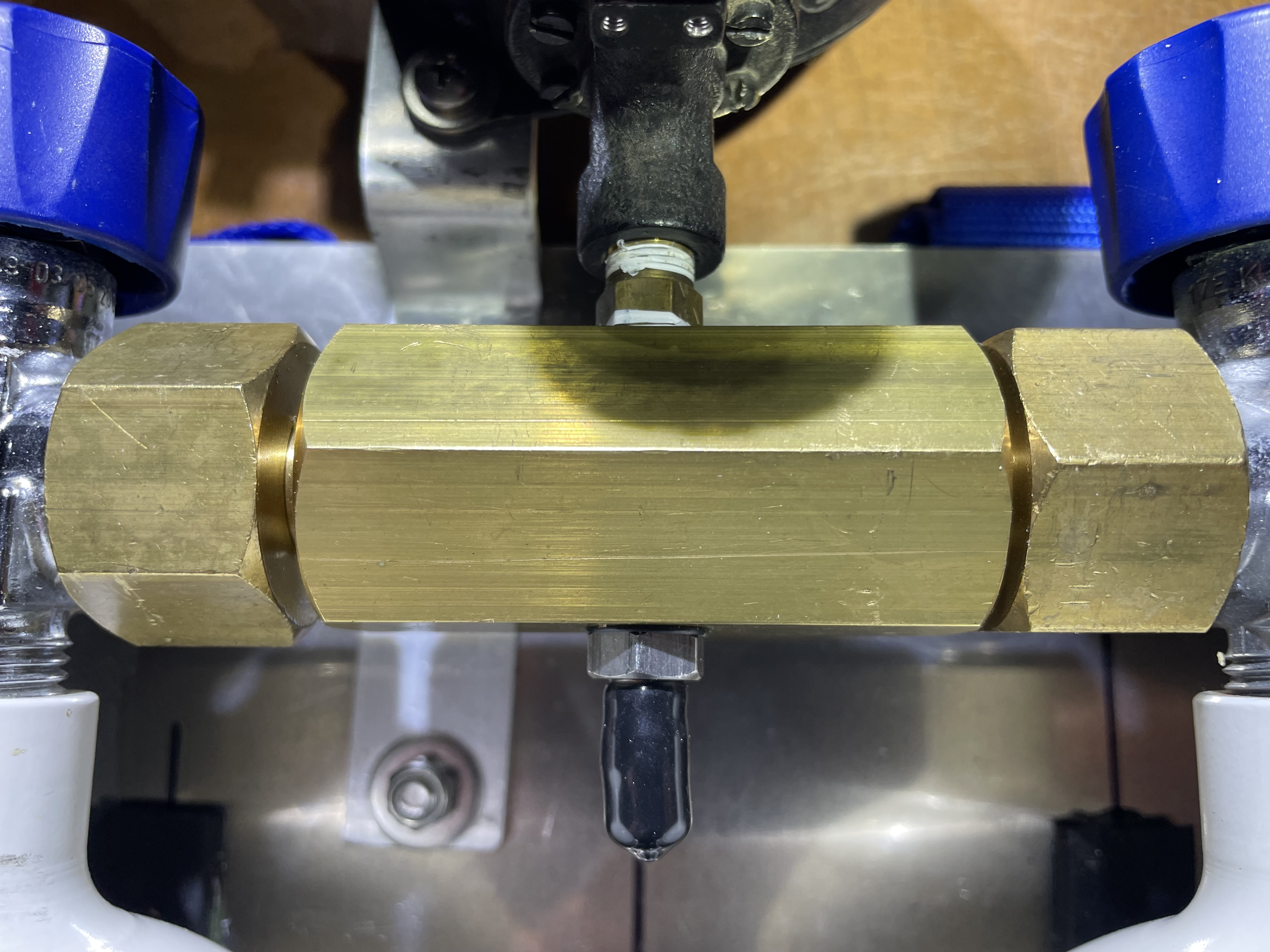
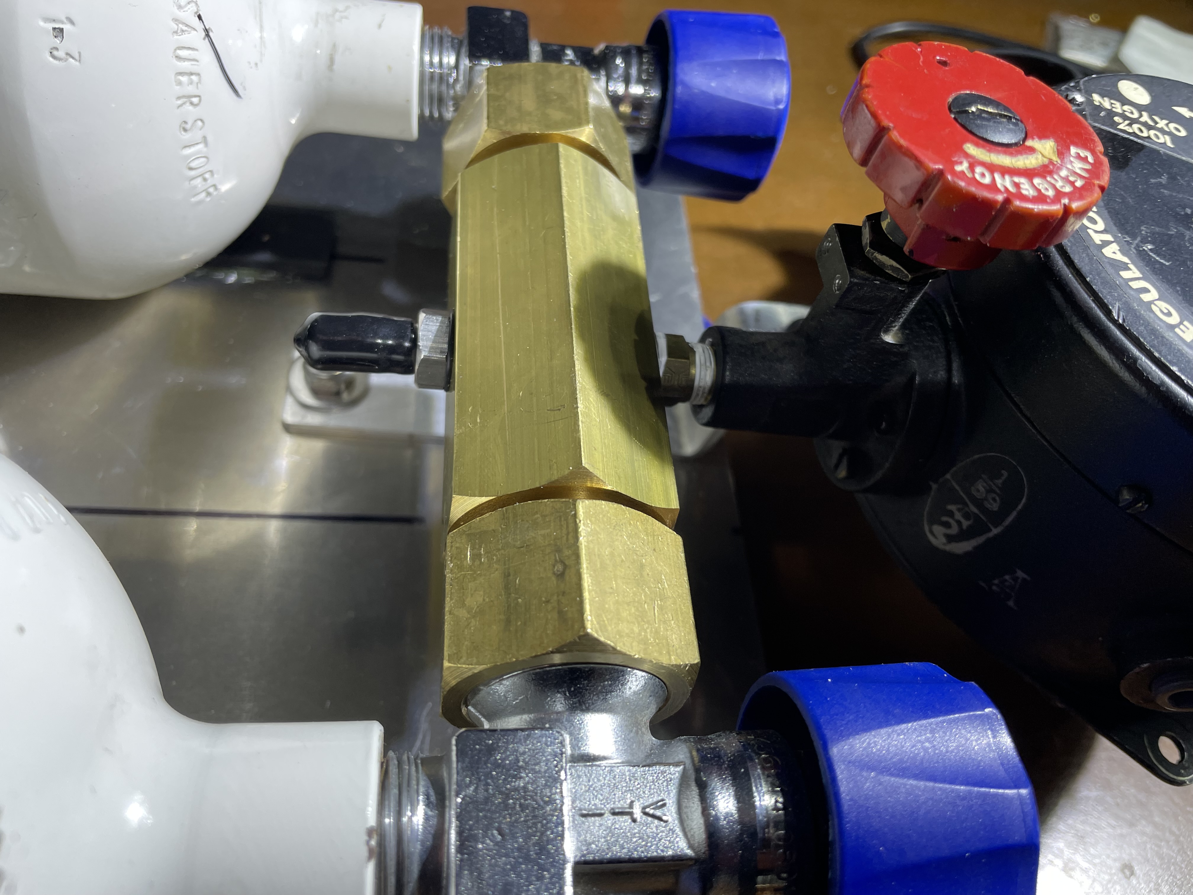
The result of the mechanical machining and the final assembly of the tanks manifold is shown in the figs. 11 and 12.
 |
 |
| Fig. 11 |
Fig. 12 |
Support plate (backplate)
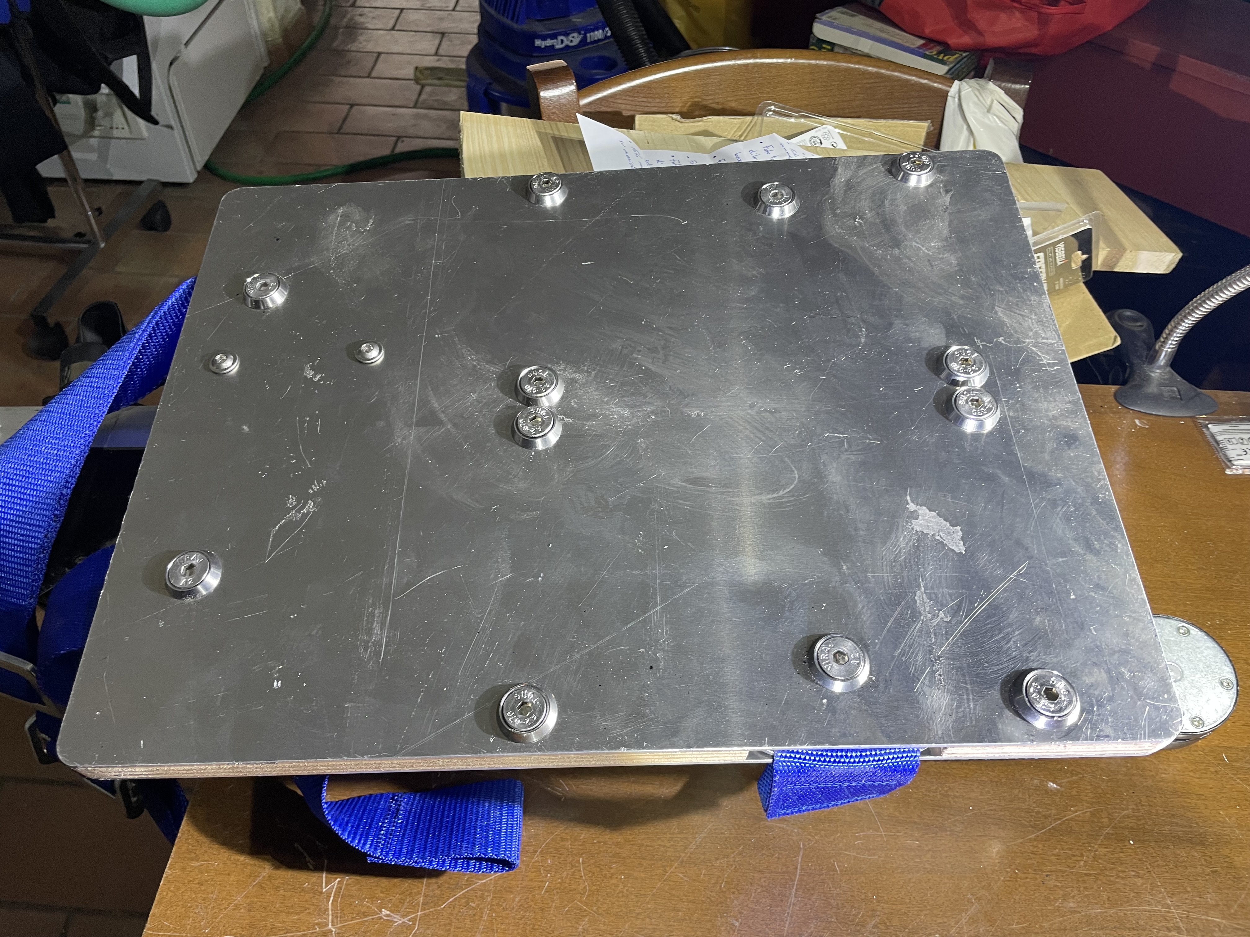
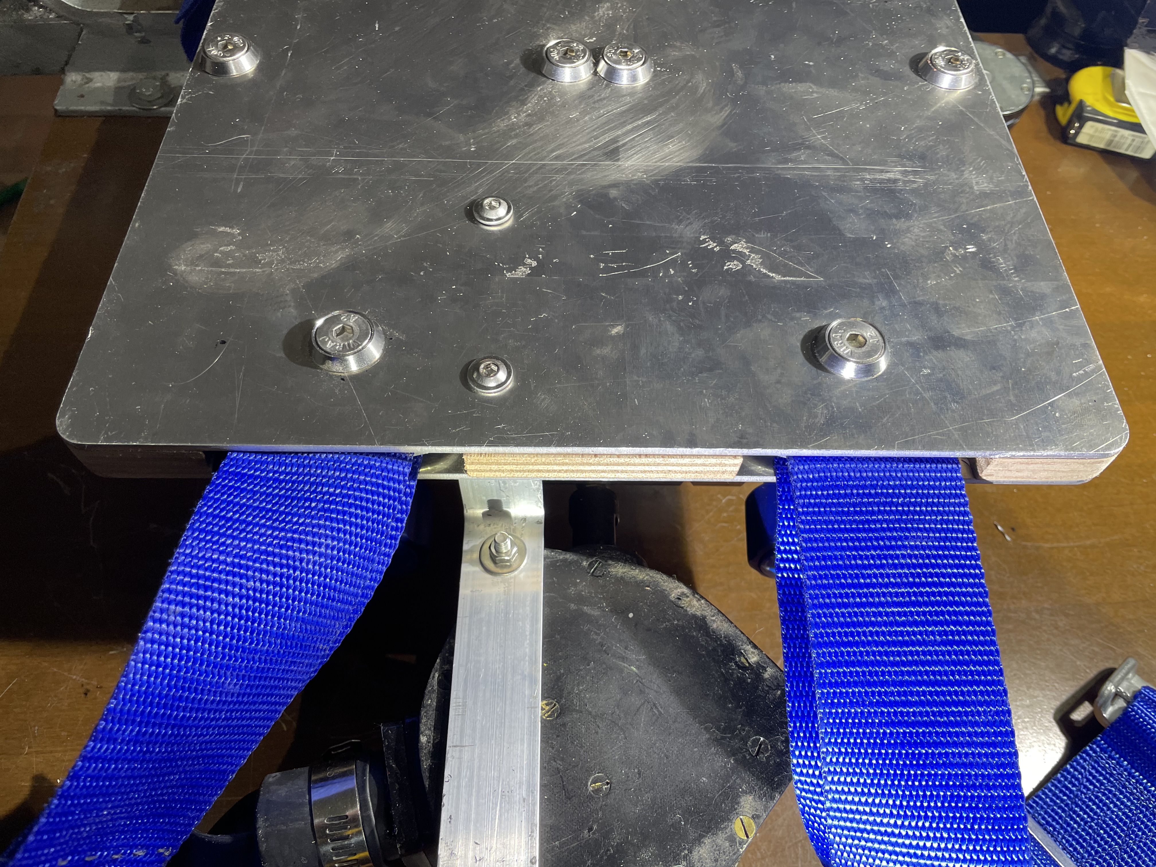
The materials identified for the building of the tanks and manifold support plate (backplate) are very similar to those described in the 1953 article except for the thicknesses which, in the original application, are in inches while, in our case, they are in millimeter. Therefore the 1/8 inch (3.175 mm) aluminum sheets became 3 mm and 1/2 inch (12.7 mm) marine plywood panel became 12 mm. Plate dimensions have also been rounded to millimeter values. The original dimensions of 12 inches X 16 inches (304.8 mm X 406.4 mm) have been updated to 300 mm X 400 mm. For the rest, the mechanical fabrication processes carried out on these materials are almost identical to those shown in the 1953 article (see figs. 13 and 14).
 |
 |
| Fig. 13 |
Fig. 14 |
Harness
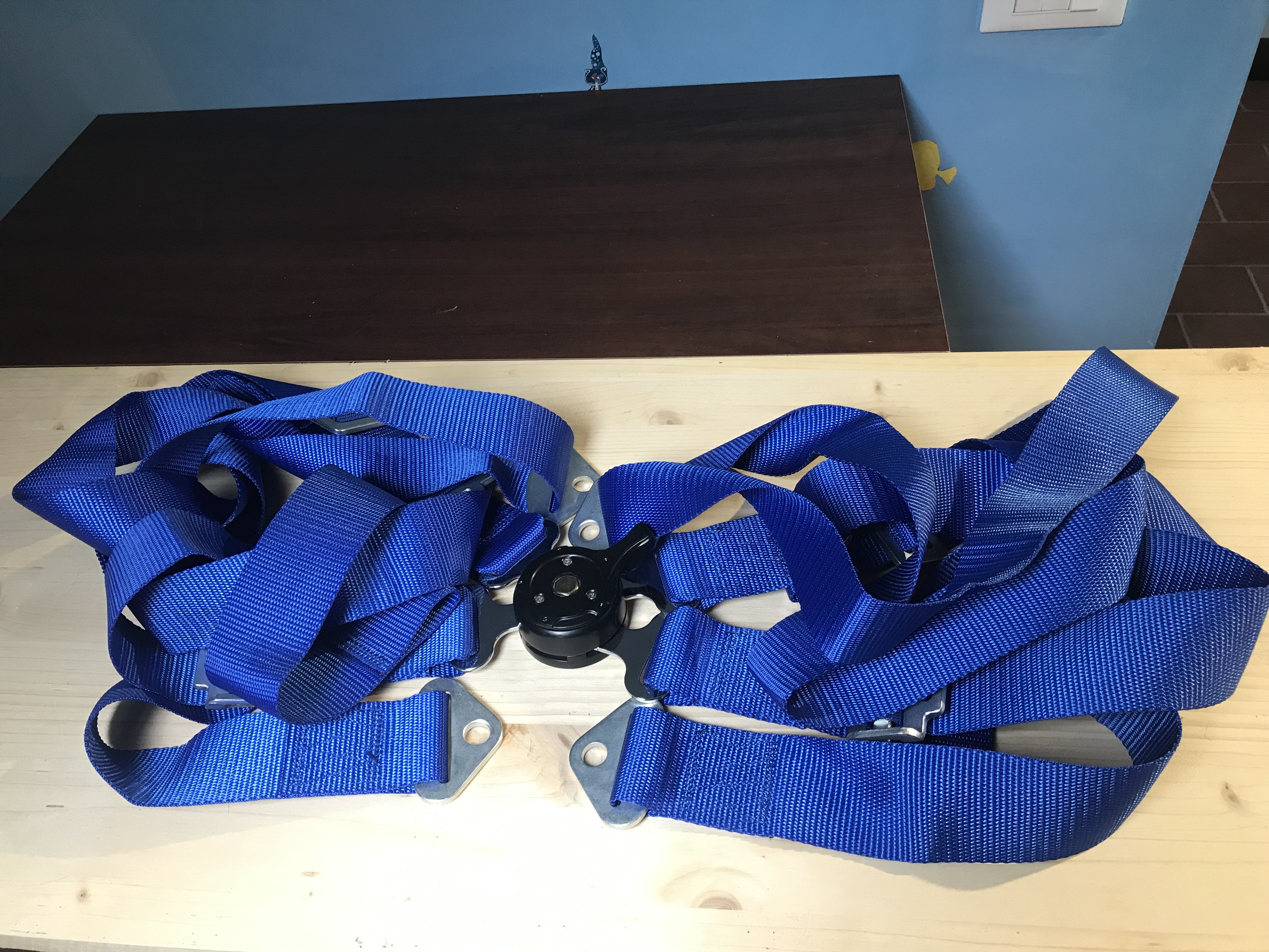
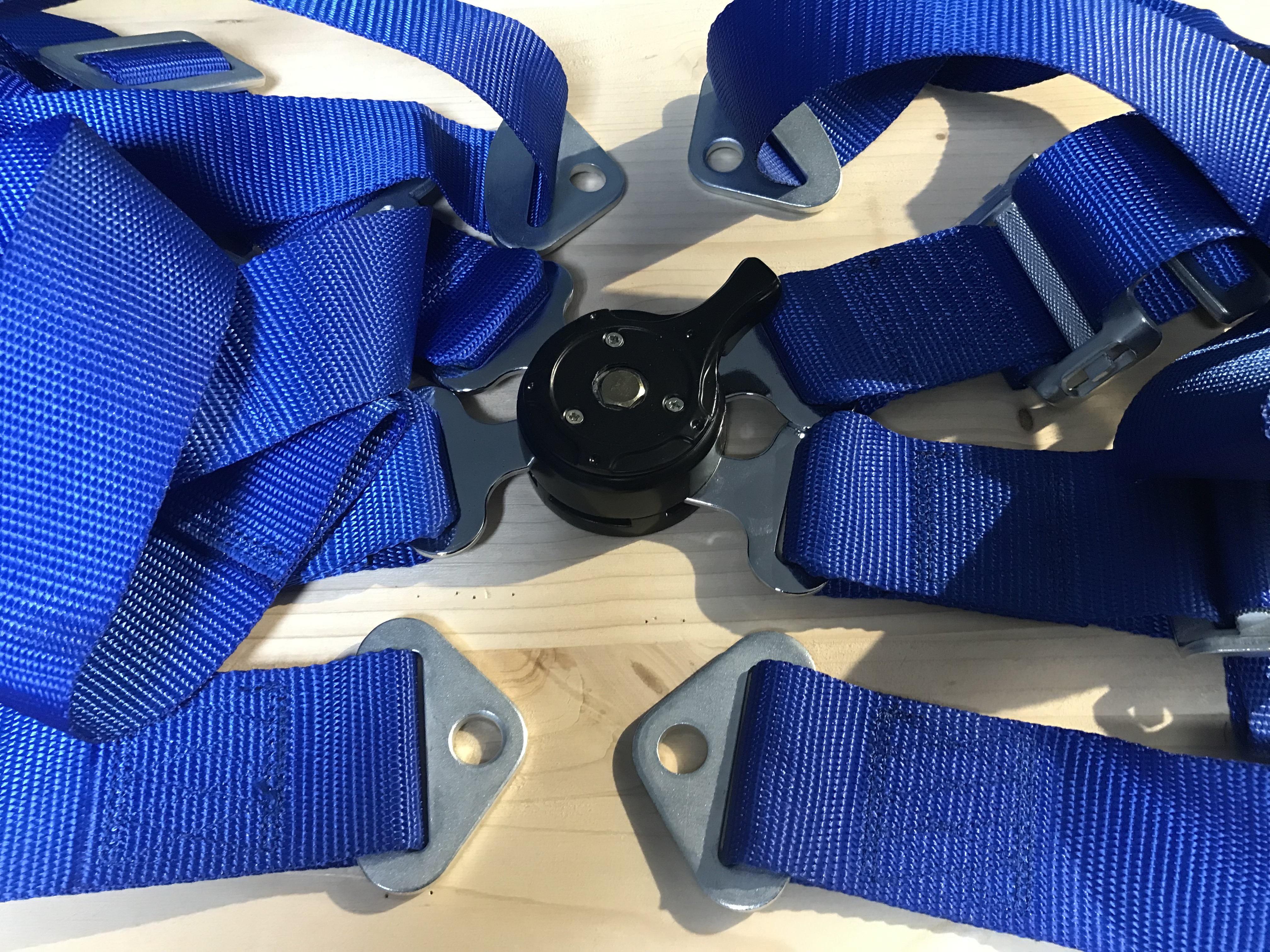
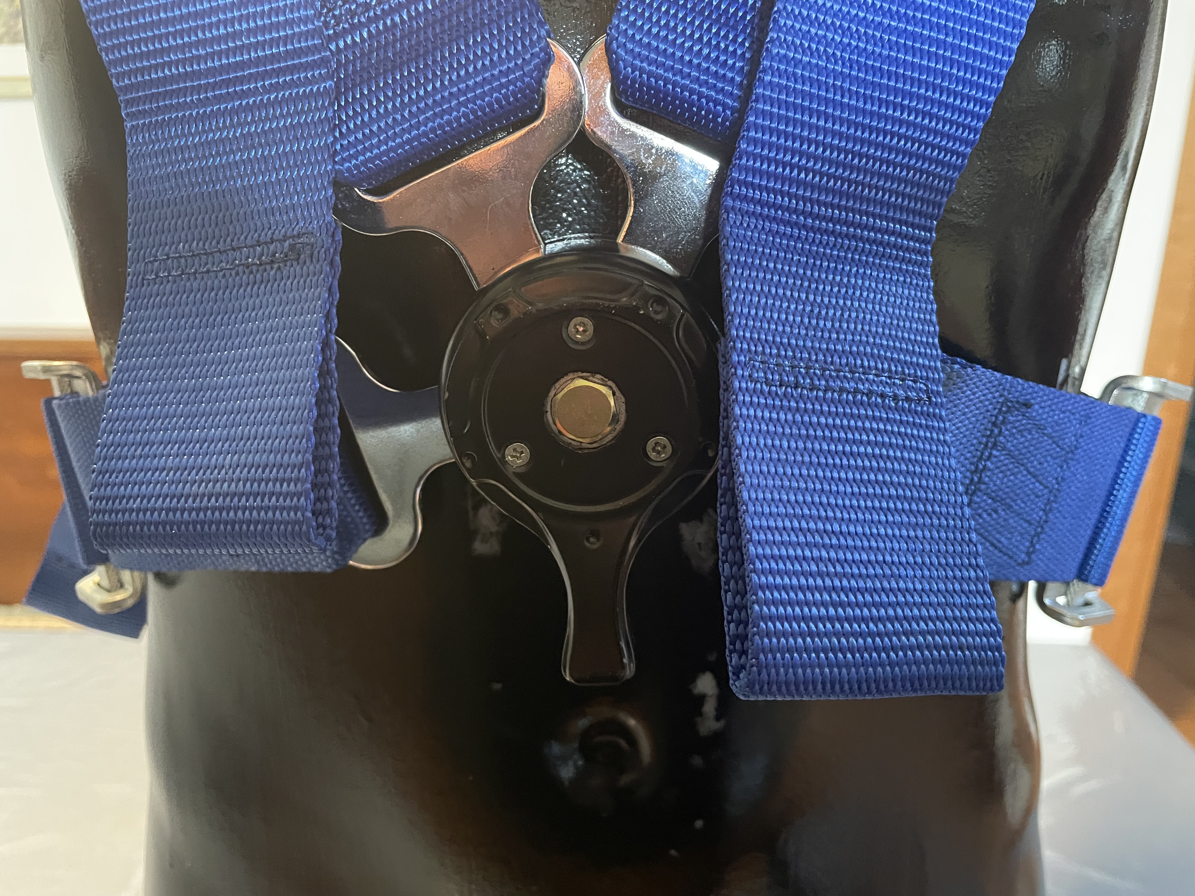
Unfortunately, despite the many searches carried out on the Internet, I was unable to find a sample of the original harness described in the article and identified by the military code AN-1201-1. This harness was mainly used in military aircraft for transporting troops. I therefore decided to use a modern 4-point harness, like the original one, but normally used in sports car applications (see figs. 15 and 16).
 |
 |
| Fig. 15 |
Fig. 16 |
Even if the central quick release connection of the harness is substantially different from the original one, its use and function is practically identical. For intellectual honesty I must recognize that the metal materials of this harness and their surface protective treatments, not having been designed for underwater use, could have problems related to corrosion in their possible prolonged use underwater. But this is certainly not my main concern now, as I certainly don't want to use this rebreather underwater but only as a display unit. Moreover, even the harness mentioned in the article was not designed for underwater use and would certainly have shown the same corrosion problems.
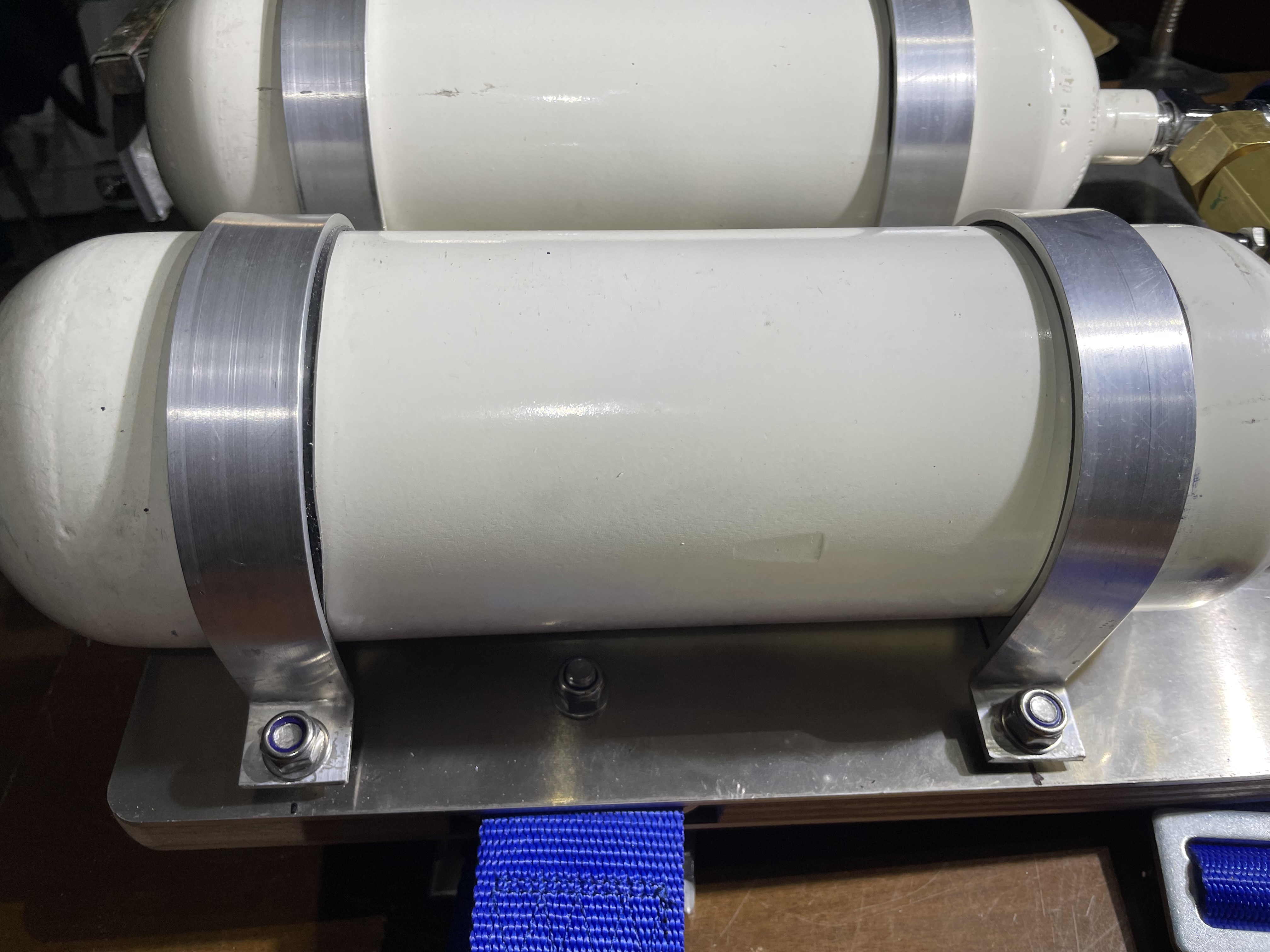
Tanks fixing bands
These bands were made using aluminum strips 25 mm wide (1 inch equal to 25.4 mm in the article) and 2 mm thick. The bands were fabricated by cutting the aluminum strips to the right size and then shaping them to precisely wrap the 2 liters tanks. The bending of the ends and their drilling to allow the installation of the connection bolts with the support plate have completed the work (see figs. 17 and 18).
 |
 |
| Fig. 17 |
Fig. 18 |
Oxygen diluter modification
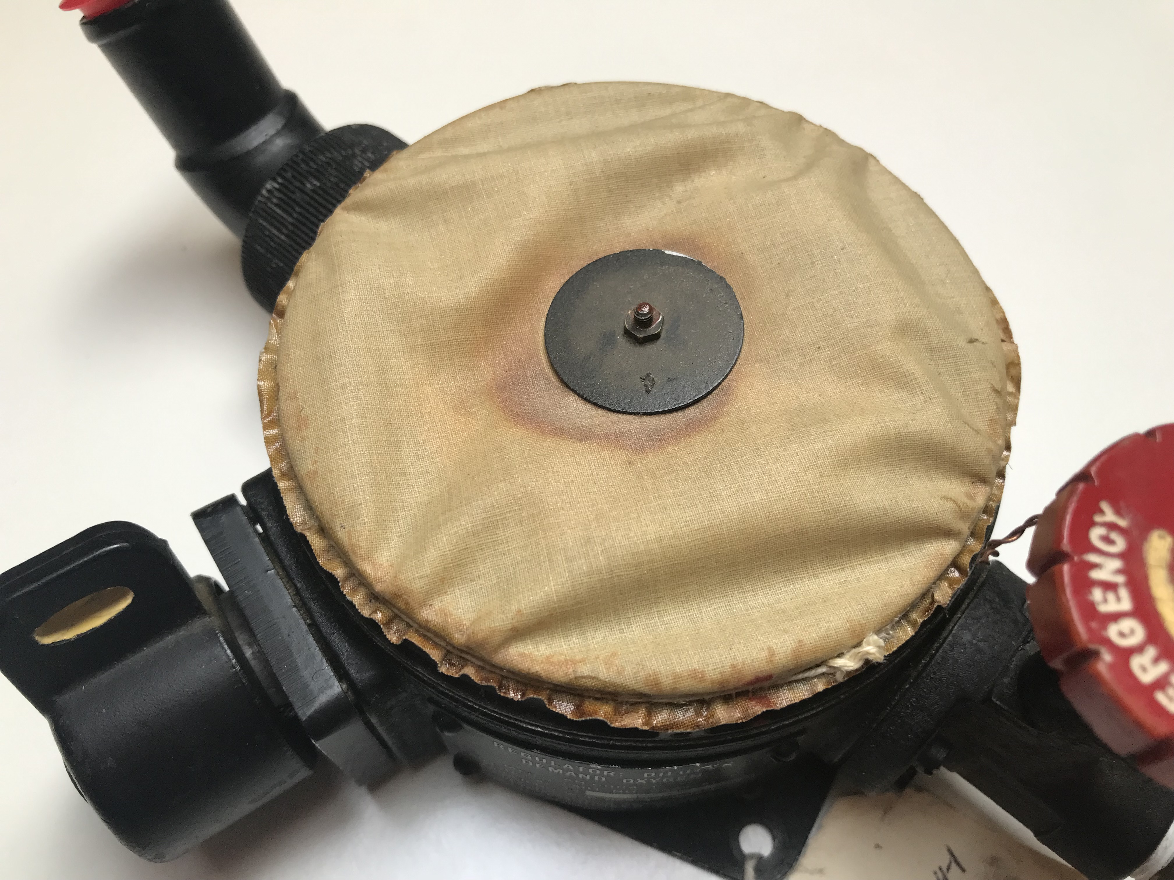
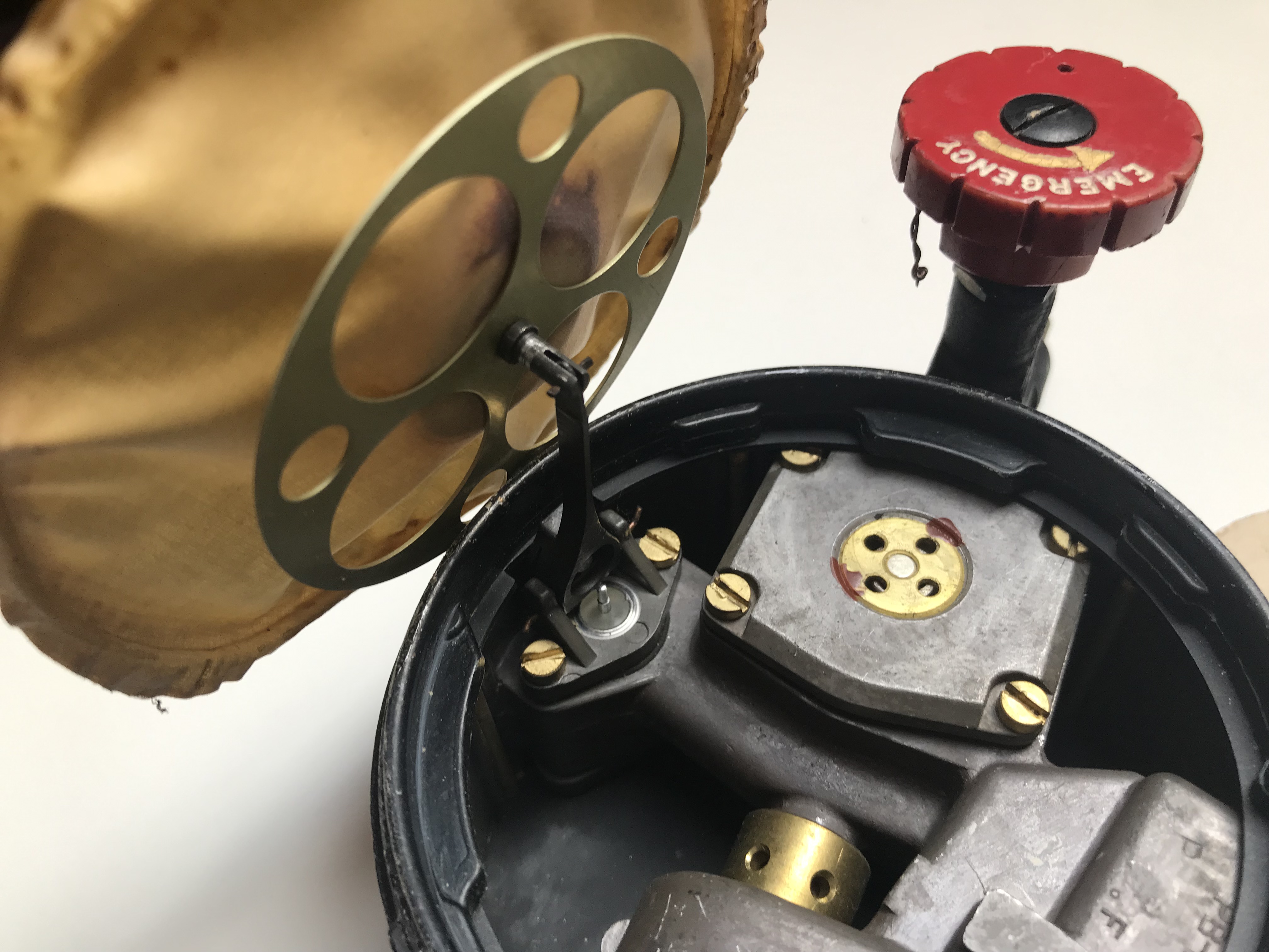
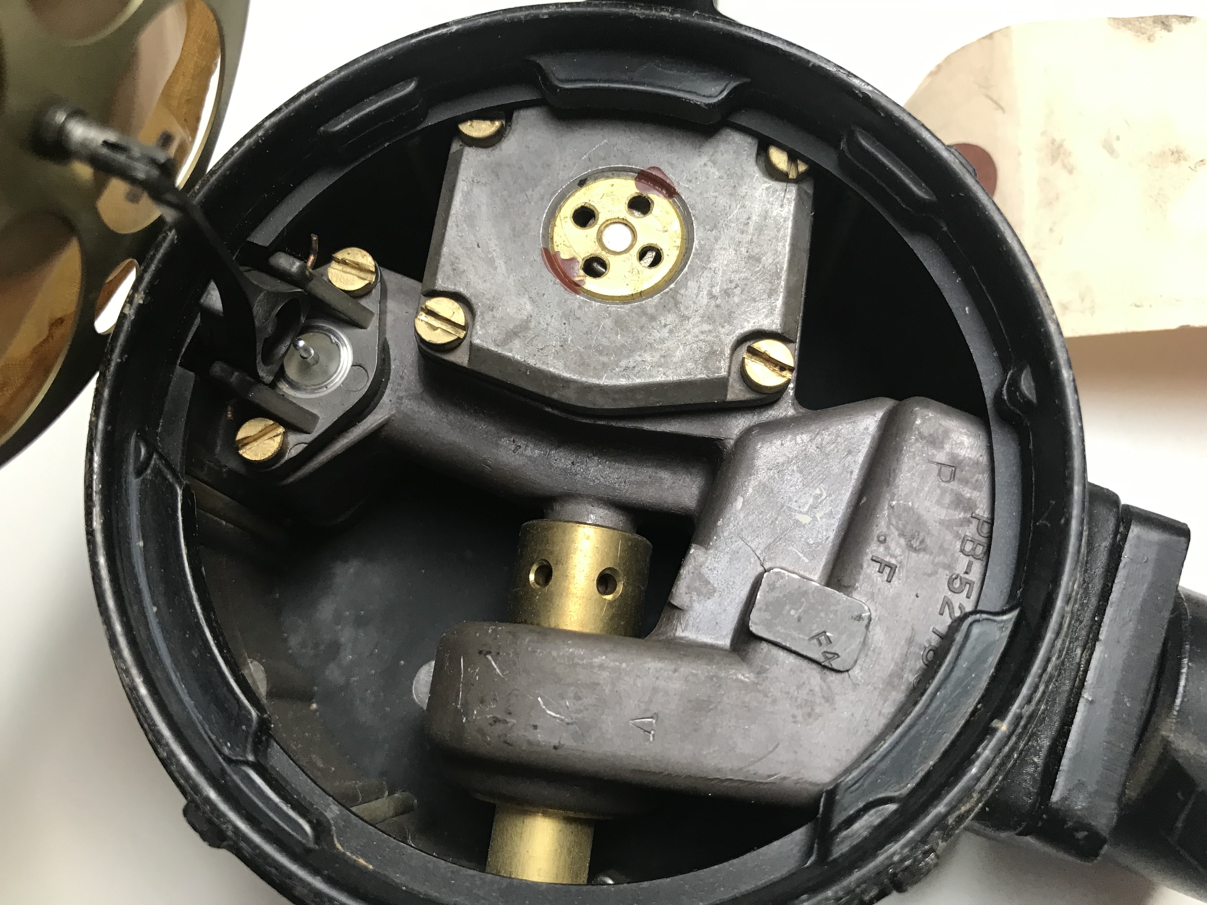
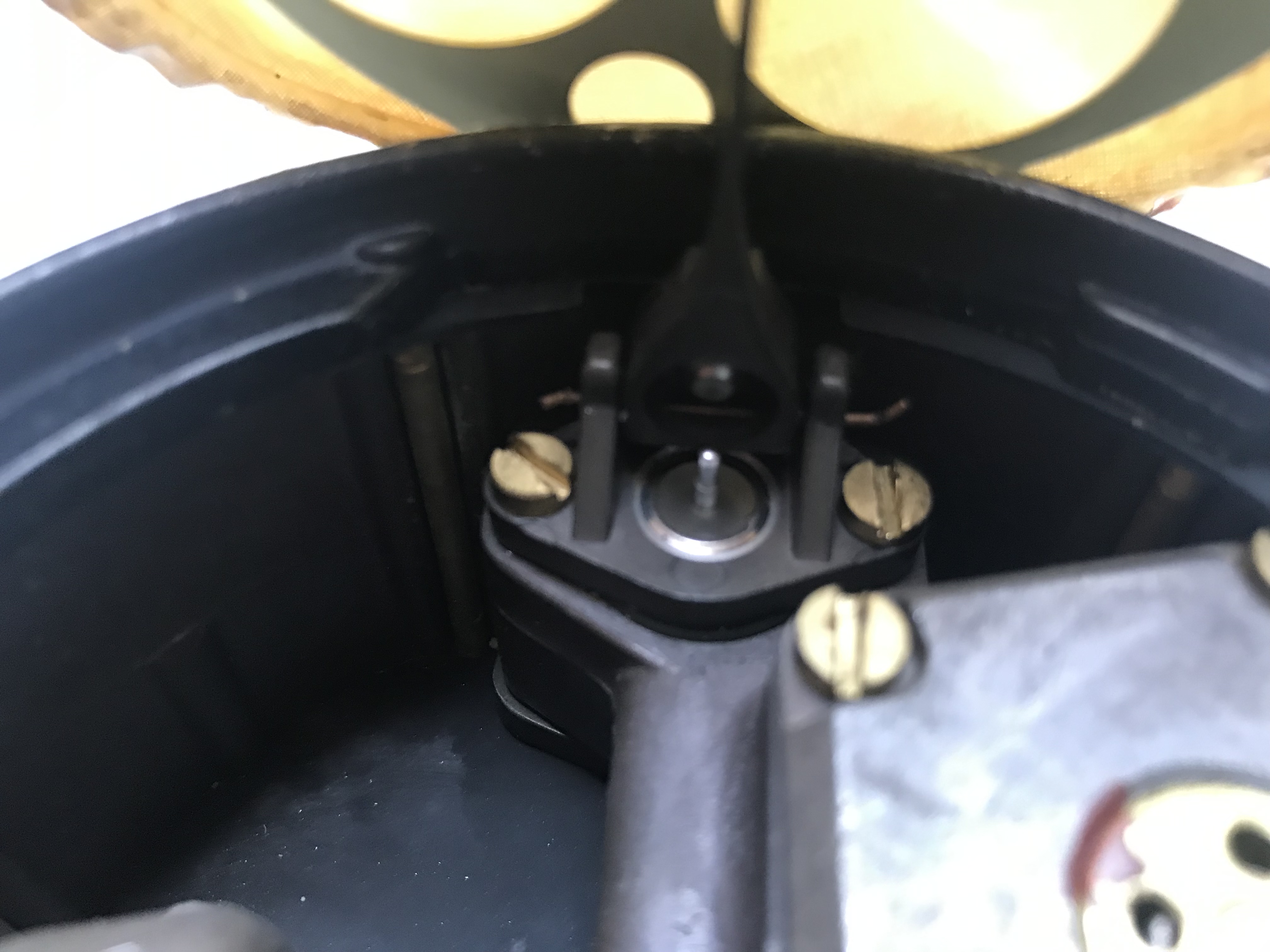
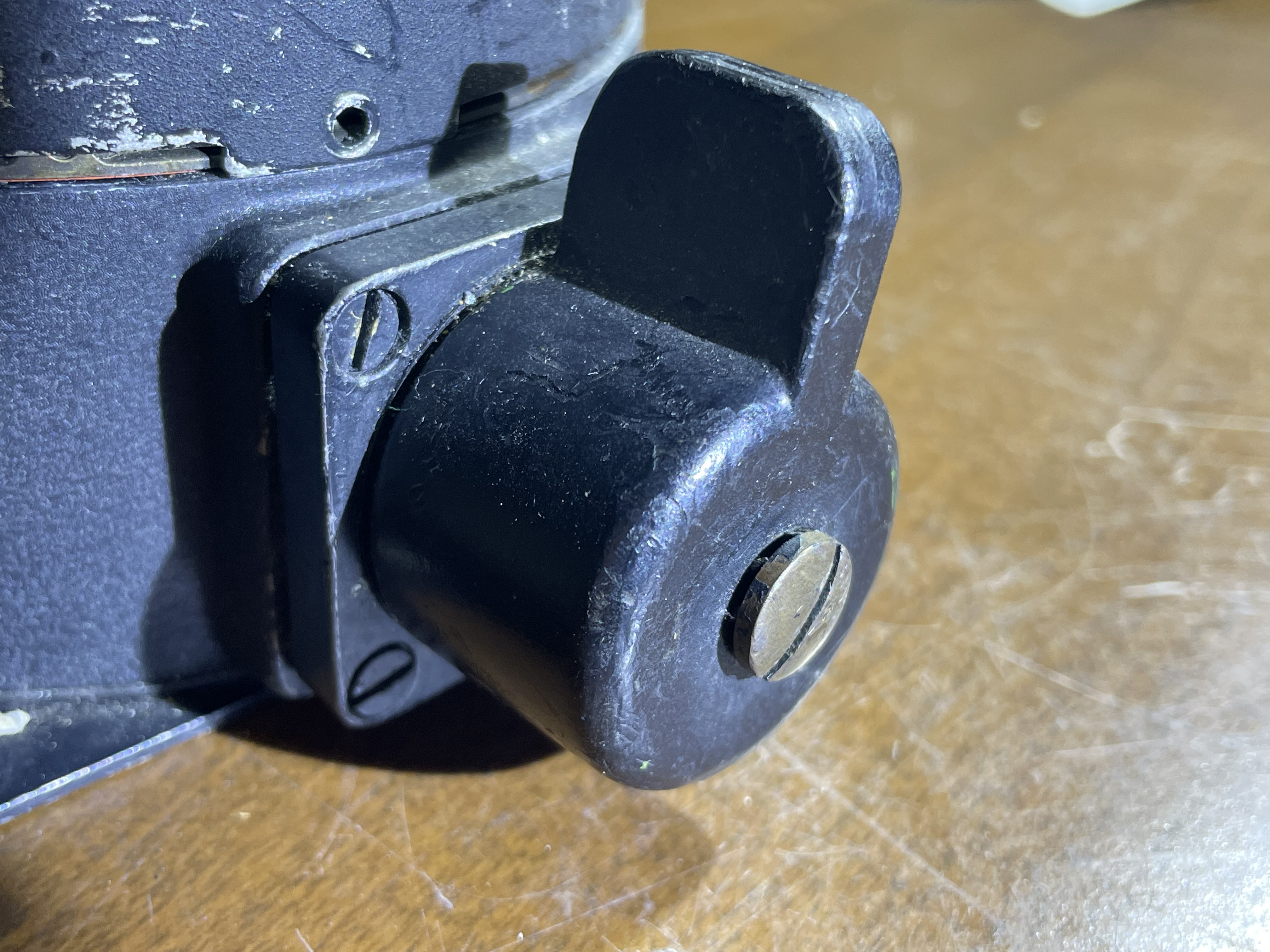
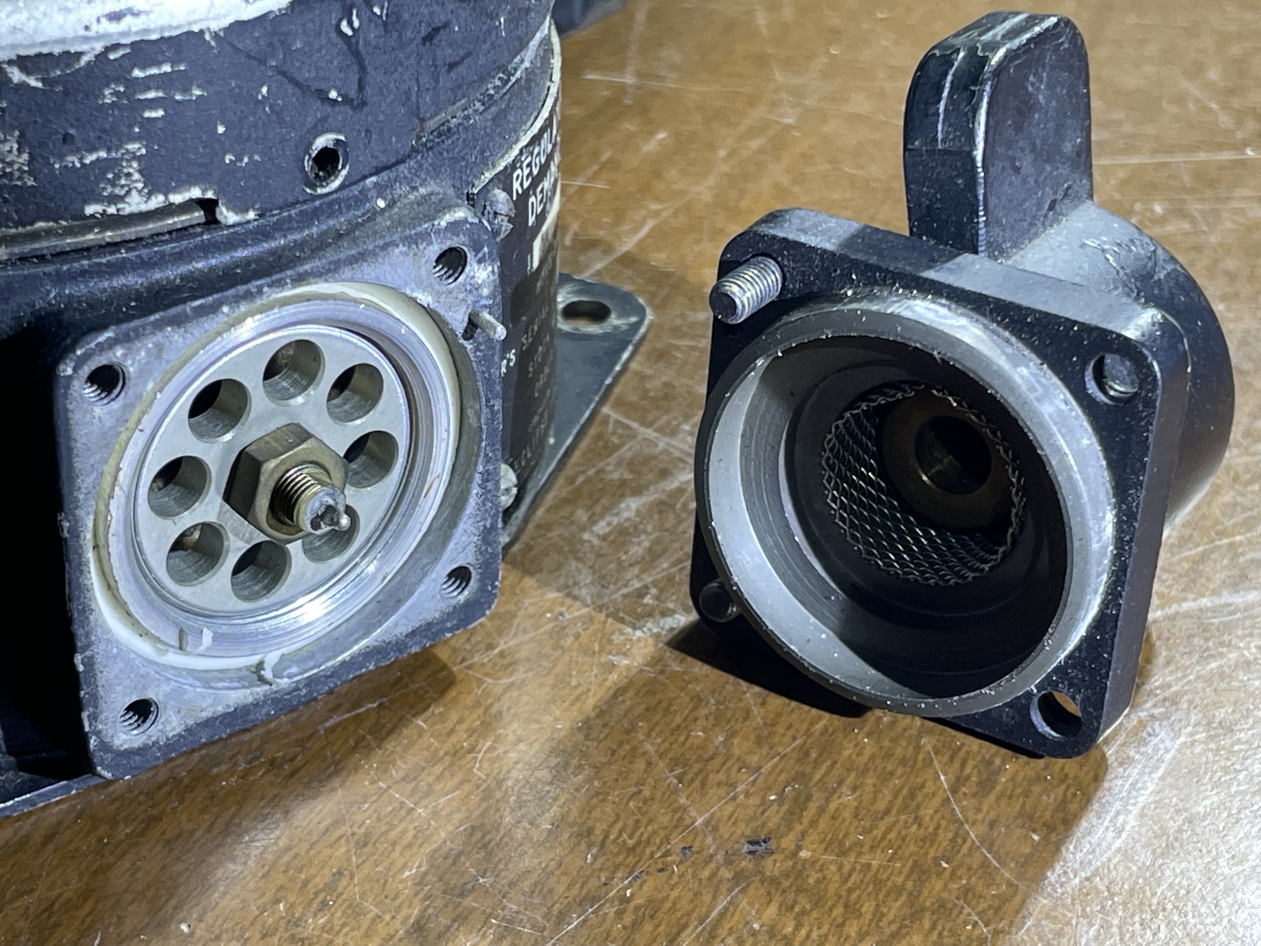
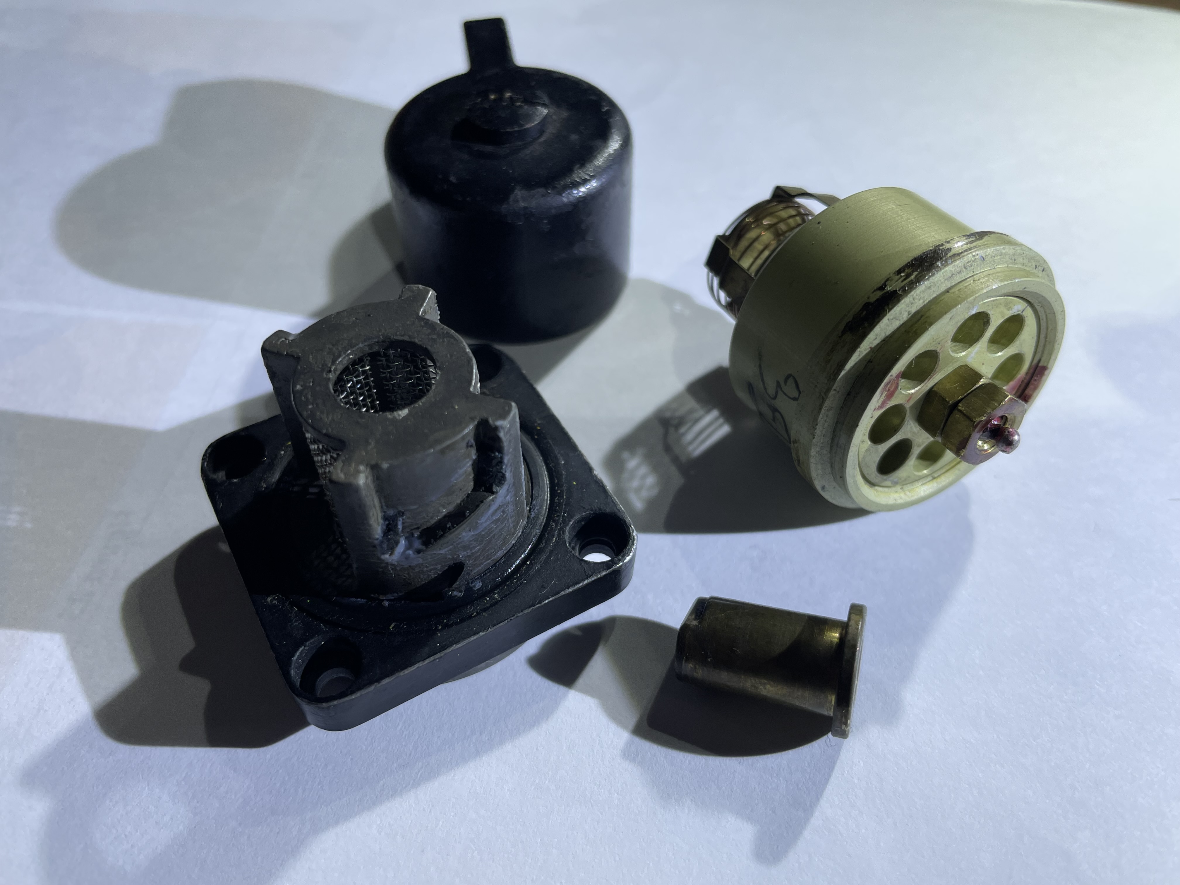
This attempt to rebuilt an air breathing apparatus following as much as possible the procedures of the 1953 Popular Science magazine article would not have made any sense if I had not found some units of the original AN-6004-1 type oxygen diluters on eBay. These devices can still be found at modest prices (from 30 to 60 dollars depending on the condition) at specialized retailers selling surplus military equipment. Compared to the devices described in the 1953 article, the units I bought have had small modifications (see figs. 19, 20, 21 and 22) which are largely understandable given the long period of time during which this device was used, but not such to compromise its performance and intended use.
 |
 |
| Fig. 19 |
Fig. 20 |
 |
 |
| Fig. 21 |
Fig. 22 |
In particular, the most important modification concerns the connection mechanism between the diaphragm (which was made in fabric as in the 1953 application) and the oxygen supply valve. The other change we noticed is the oxygen flow regulation system which is no longer a screw but requires a special tool to change its calibration.
The modification actions undertaken were as identical as possible to those described in the article, namely the following:
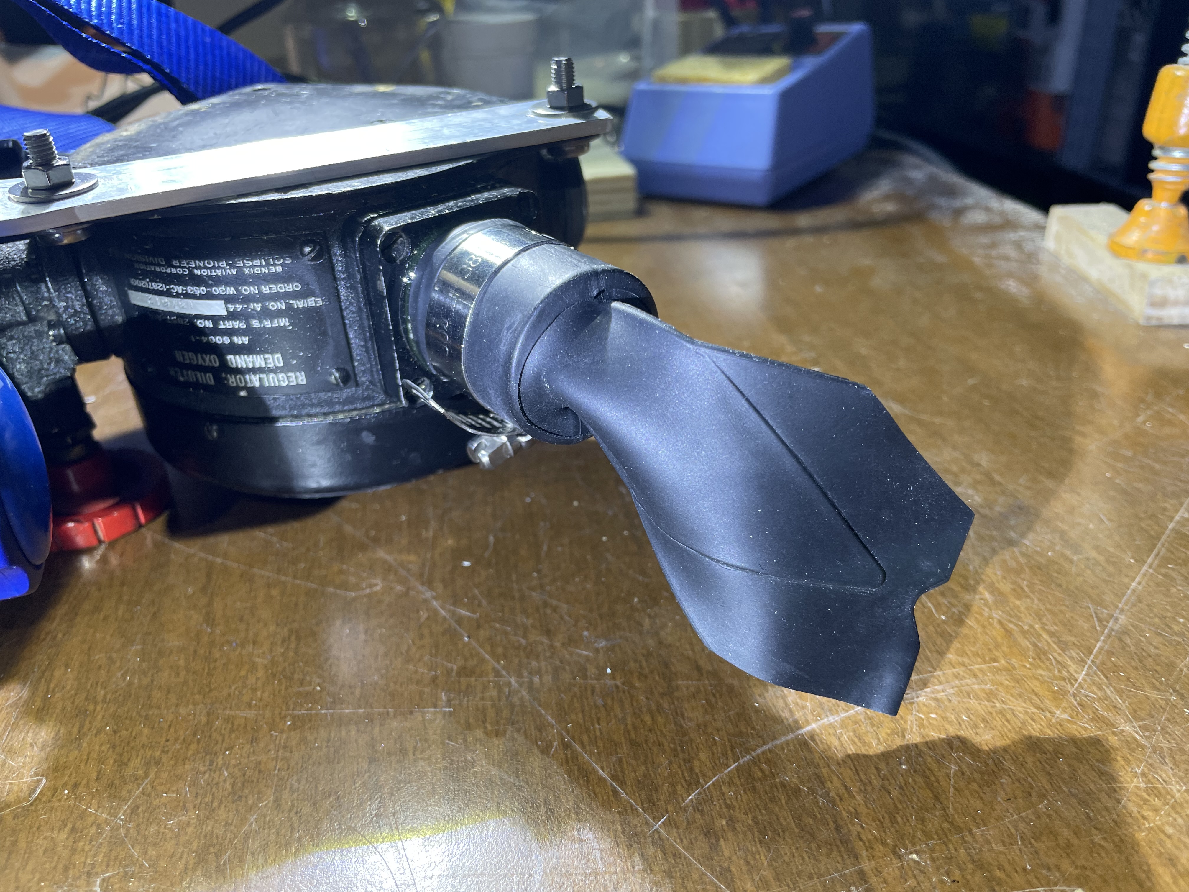
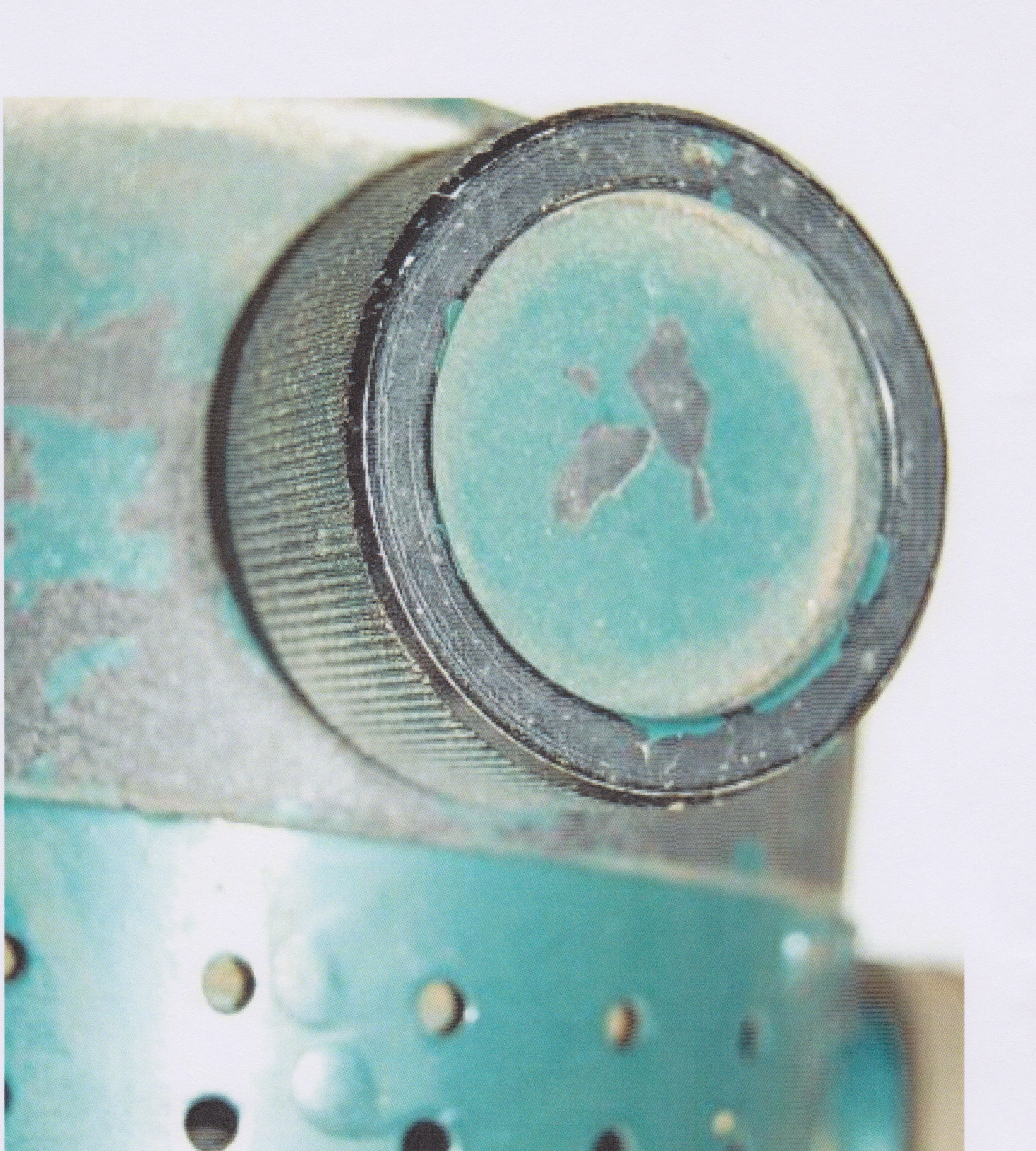
- Transformation of the dilution control and air inlet knob into a simple exhaled air discharge outlet provided with a duckbill valve (see figs. 23, 24, 25 and 26).
 |
 |
| Fig. 23 |
Fig. 24 |
 |
 |
| Fig. 25 |
Fig. 26 |
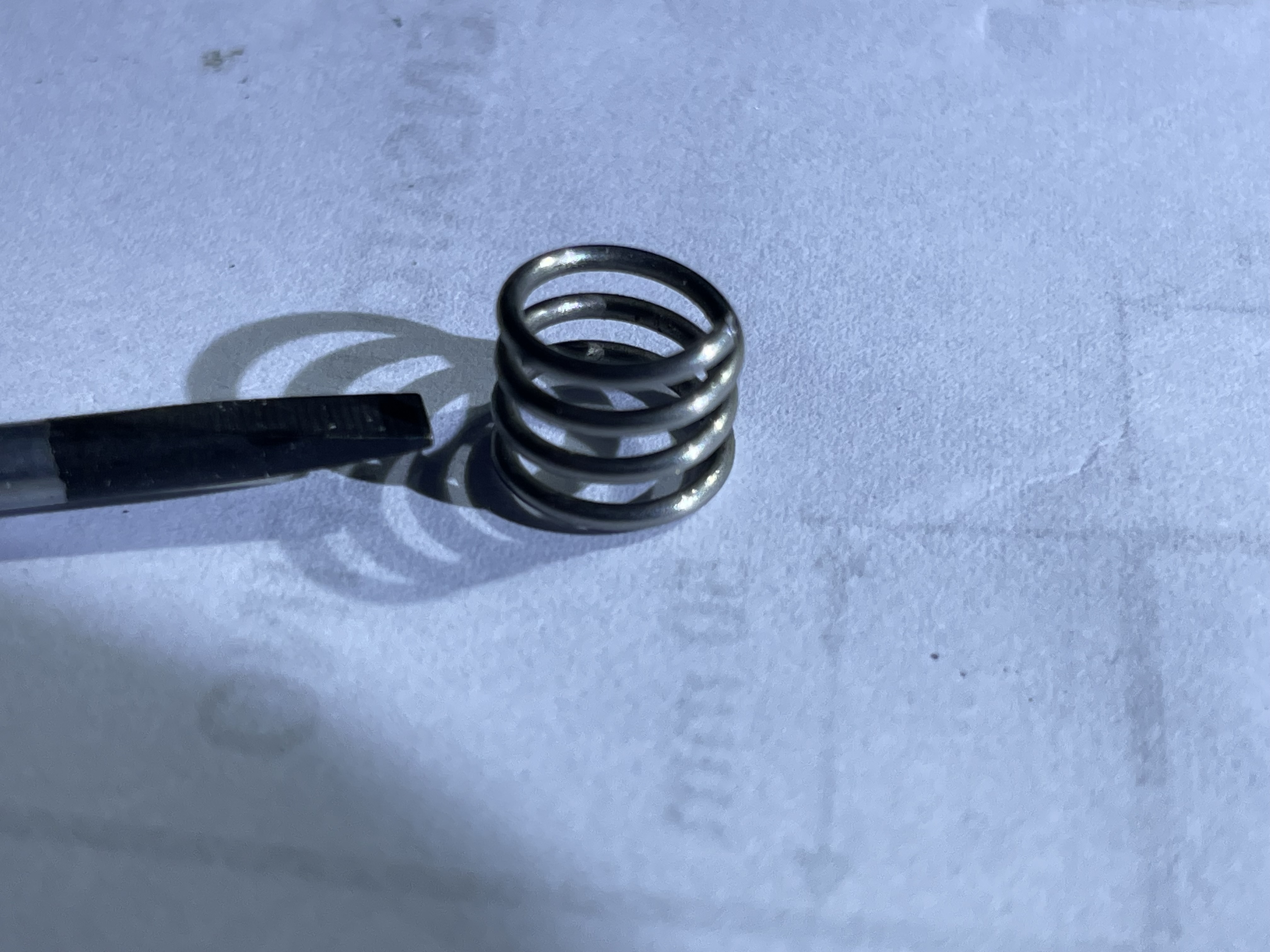
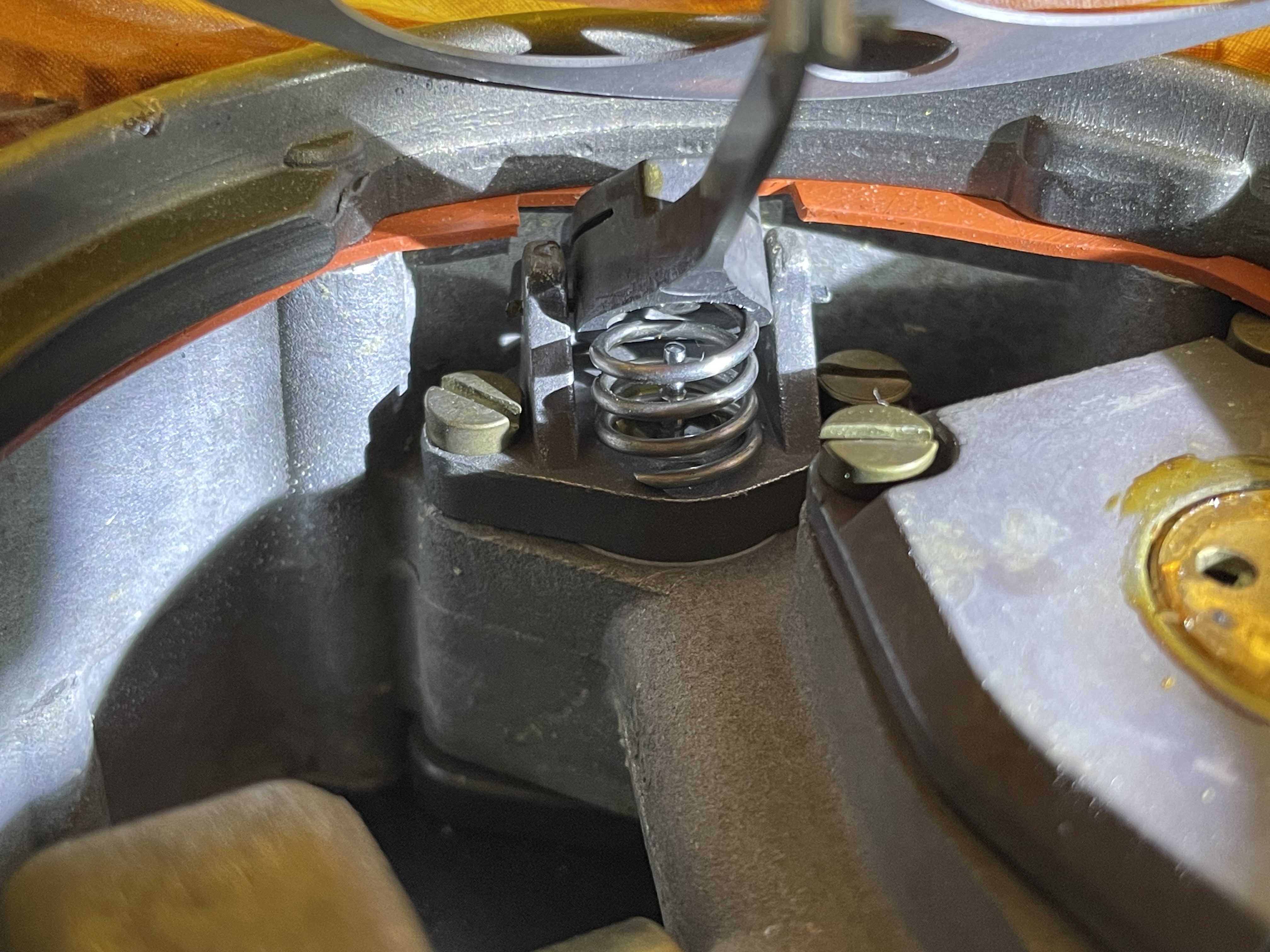
- Installation of a stainless steel spring to increase the resetting force of the diaphragm and delivery valve (see figs. 27 and 28).
 |
 |
| Fig. 27 |
Fig. 28 |
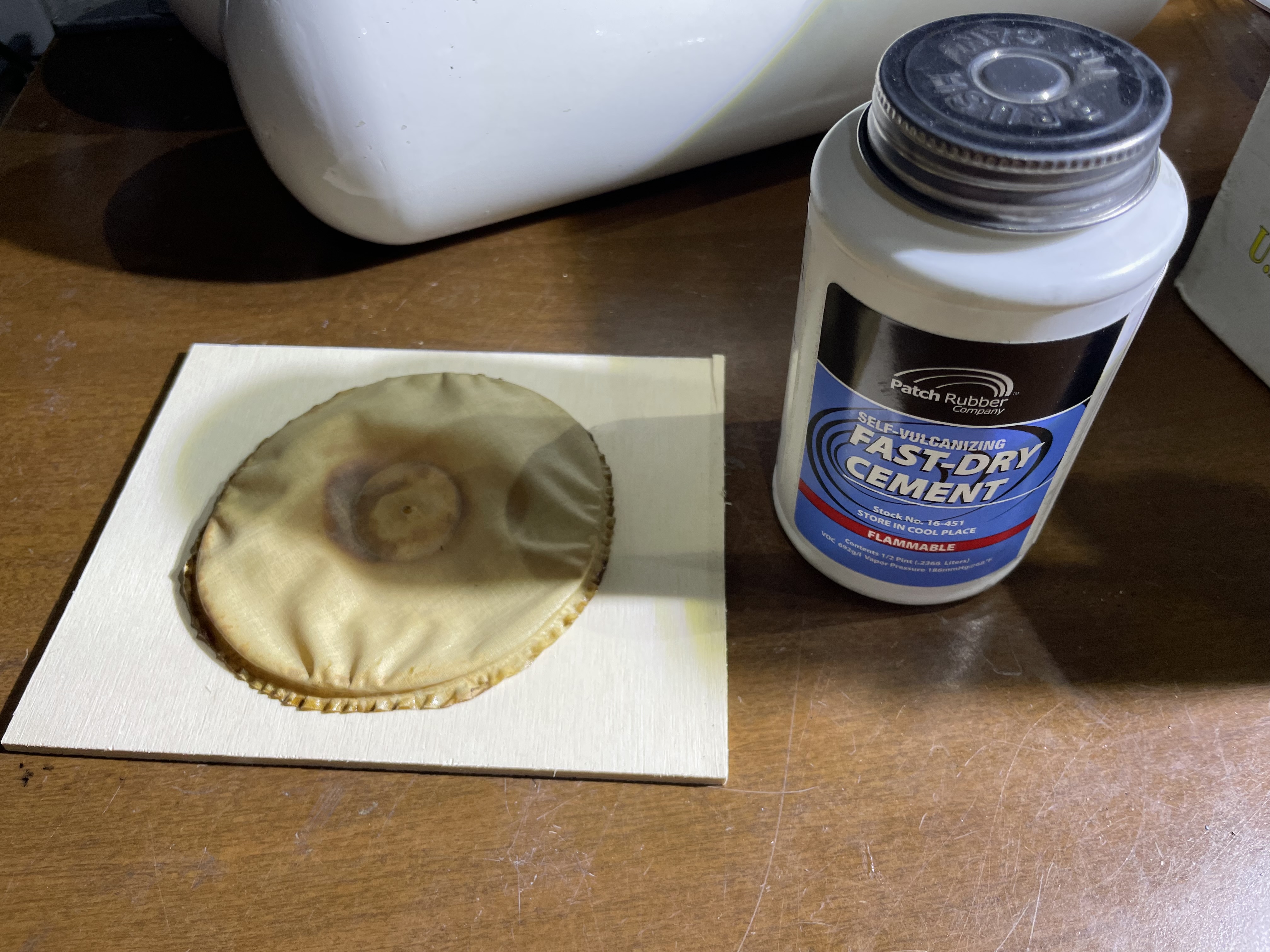
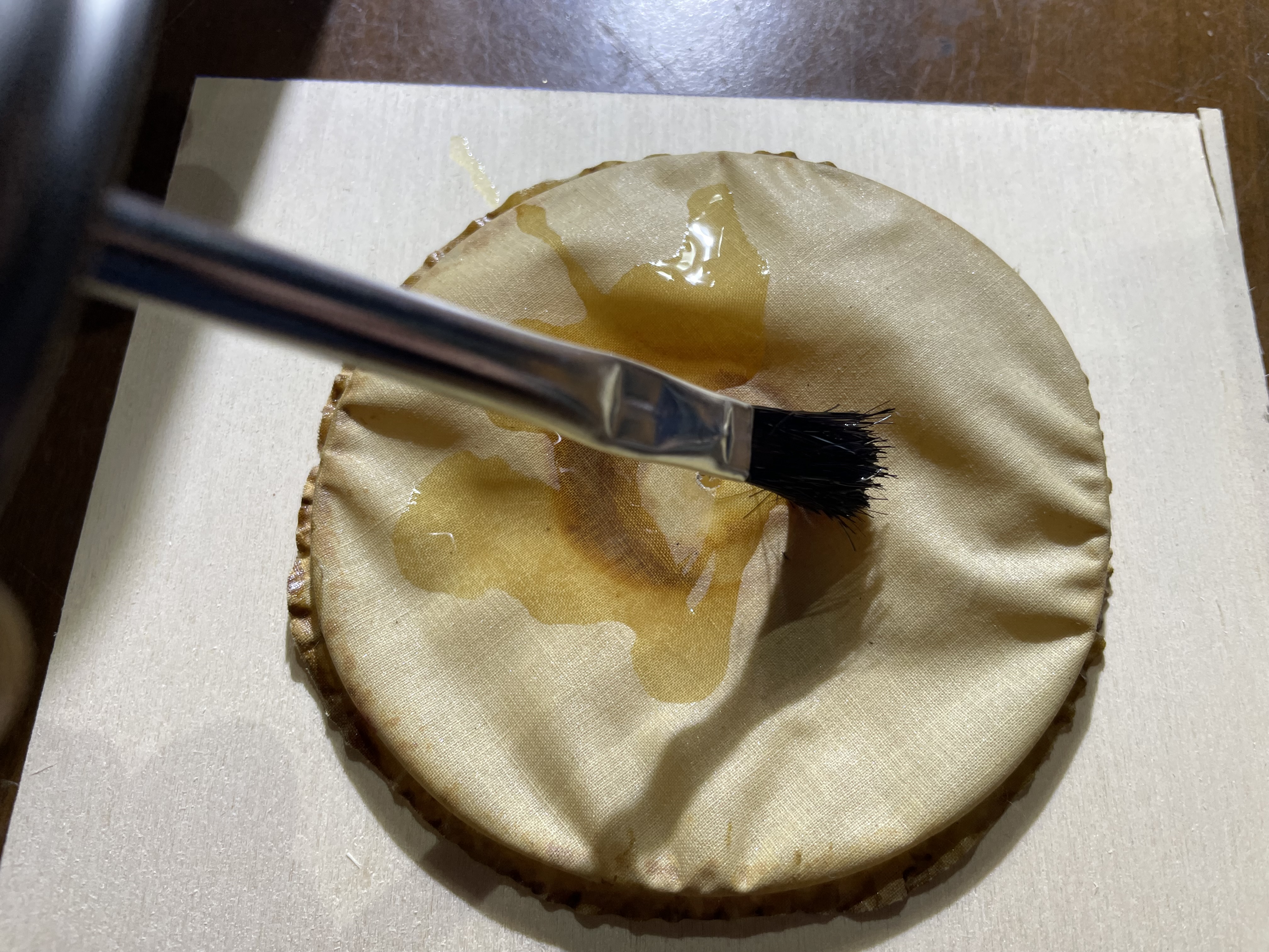
- Waterproofing the diaphragm by applying a special glue defined as rubber cement in the article (see figs. 29 and 30).
 |
 |
| Fig. 29 |
Fig.30 |
The device, after the modifications, appears as shown in the figs. 31 and 32.
 |
 |
| Fig. 31 |
Fig. 32 |
Breathing circuit
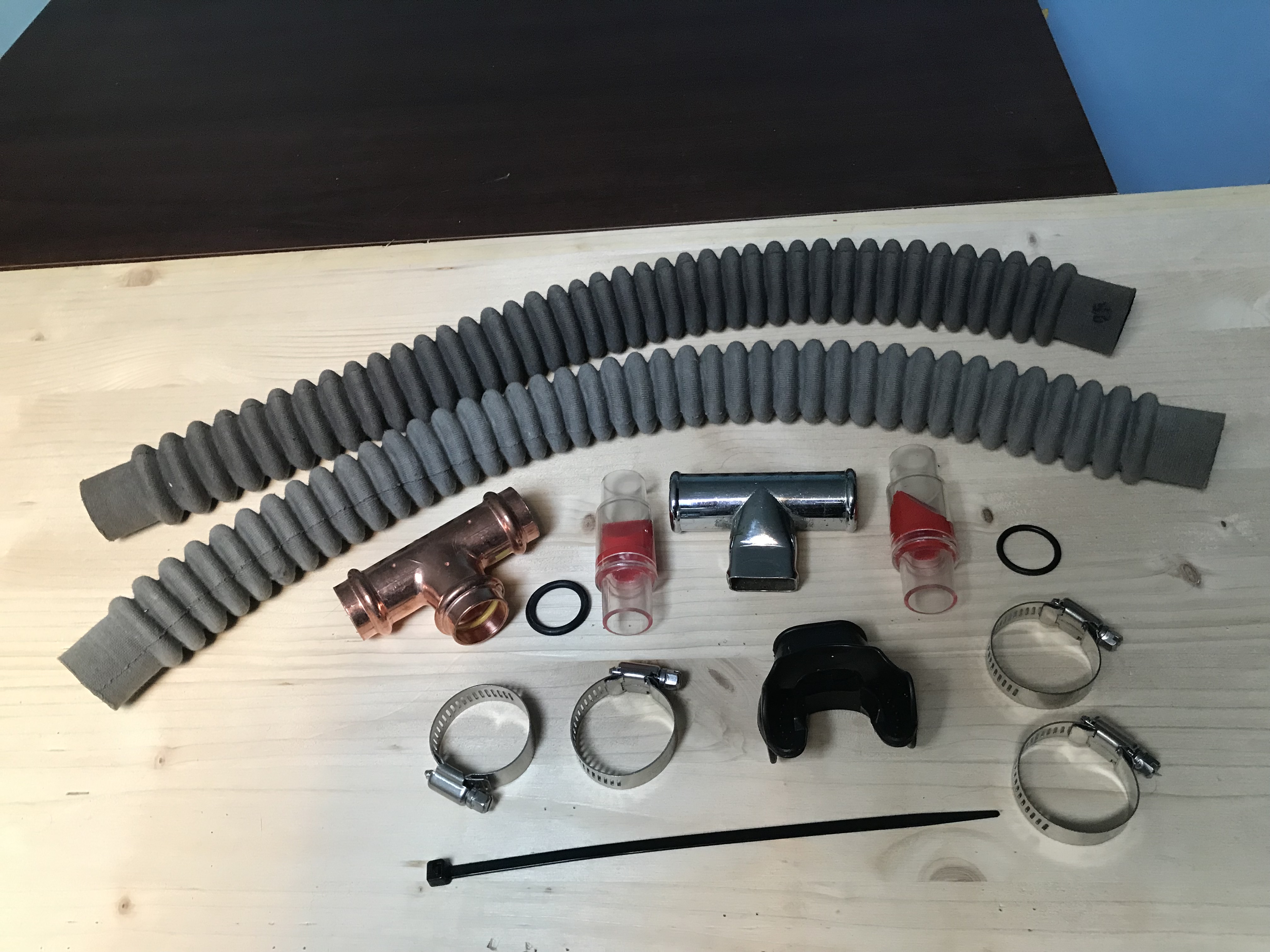
The components used in the construction of this part of the breathing apparatus are shown in fig. 33.
 |
| Fig. 33 |
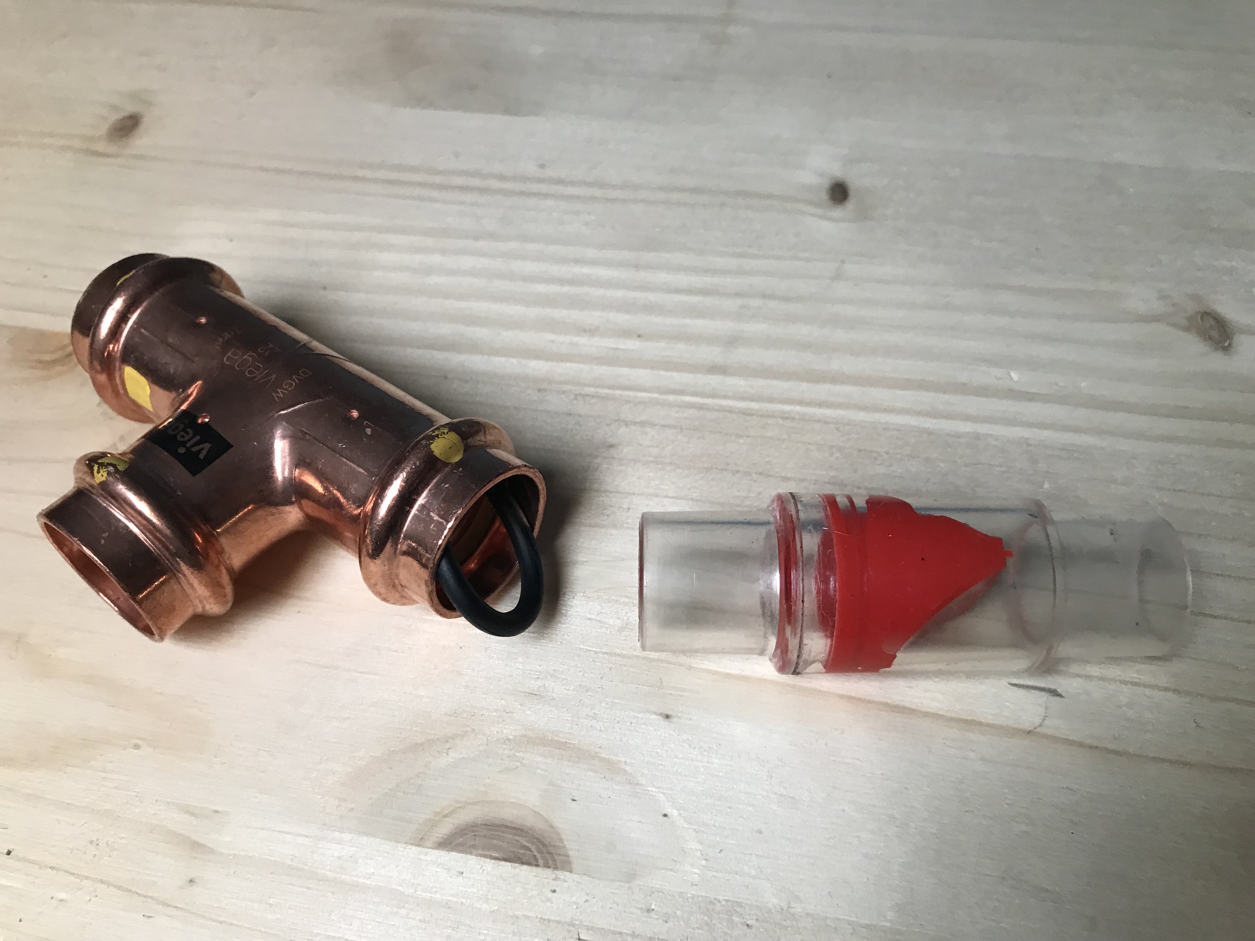
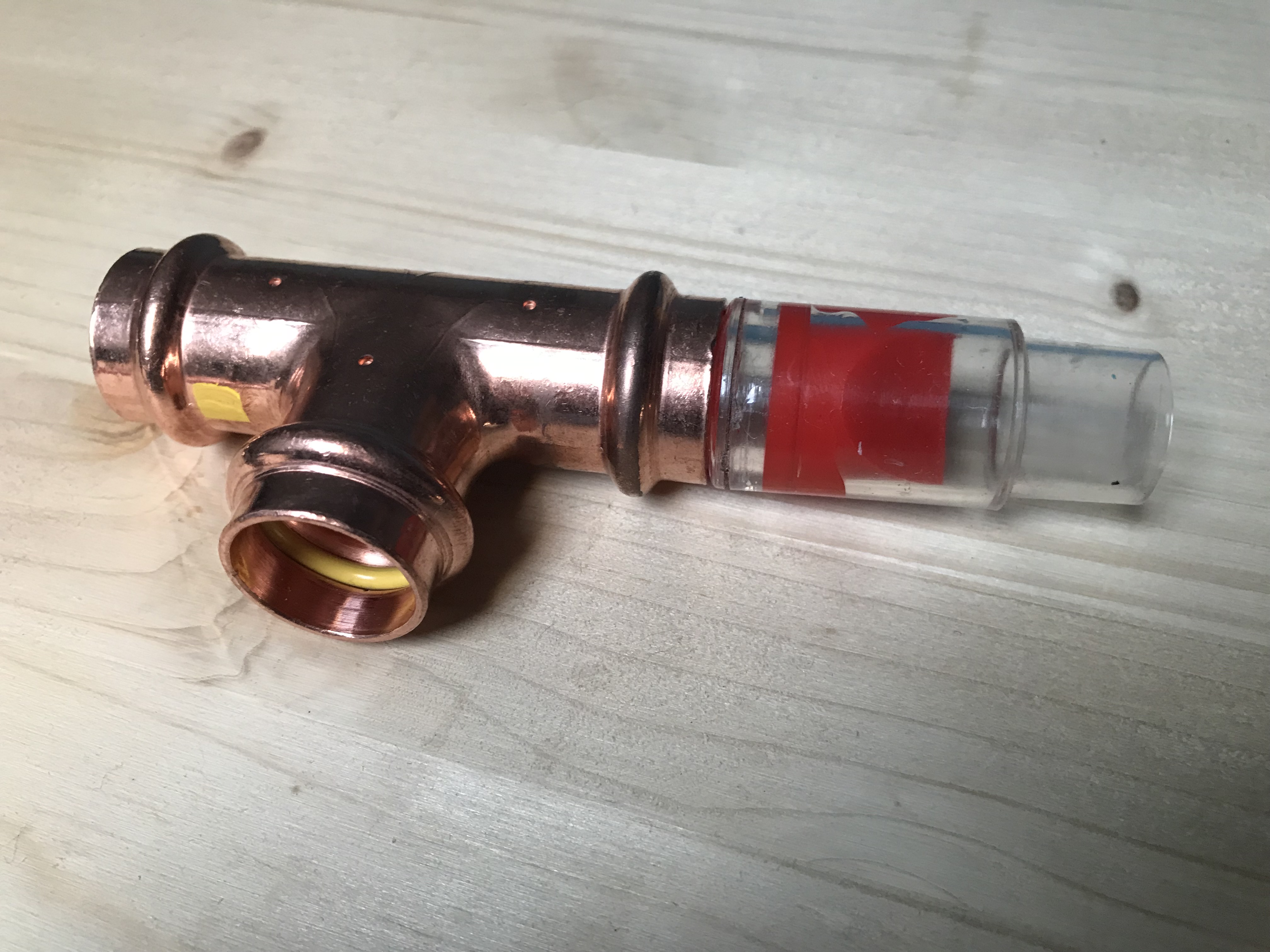
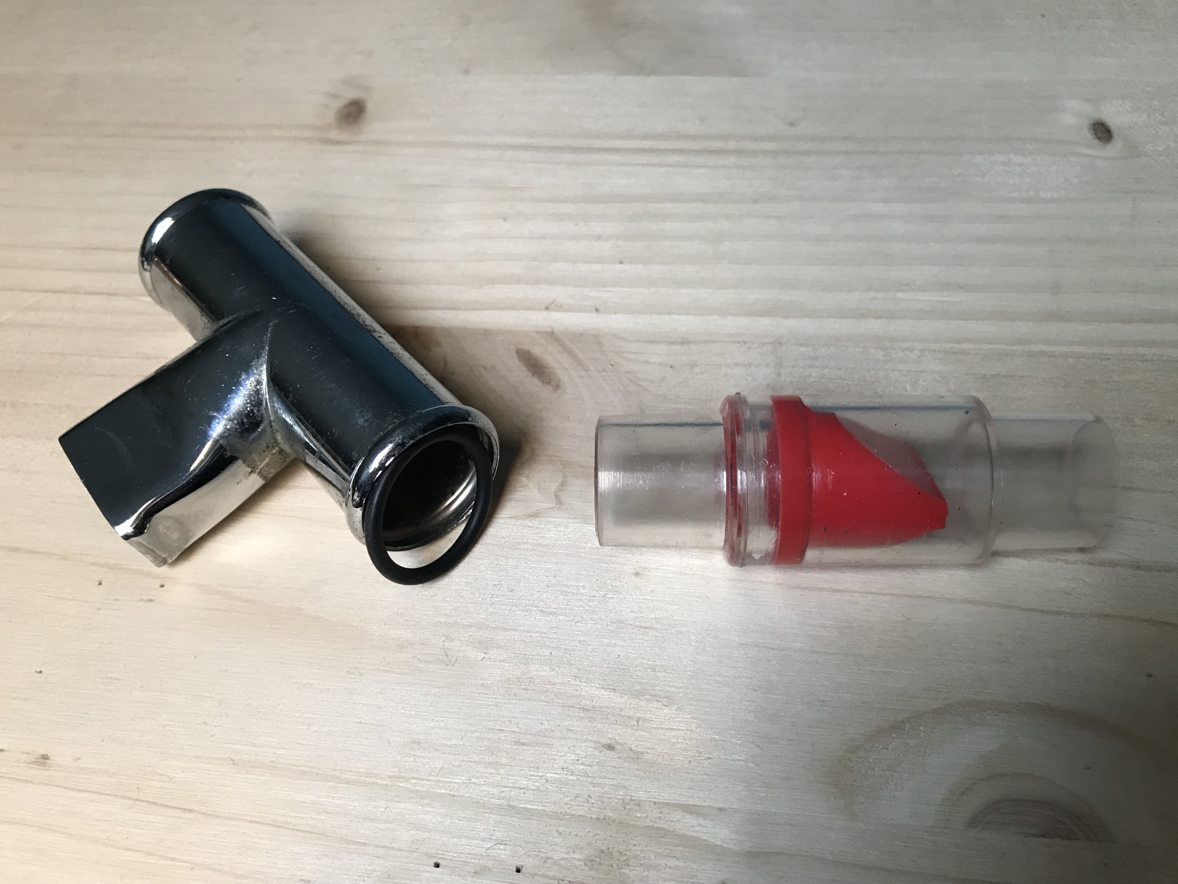
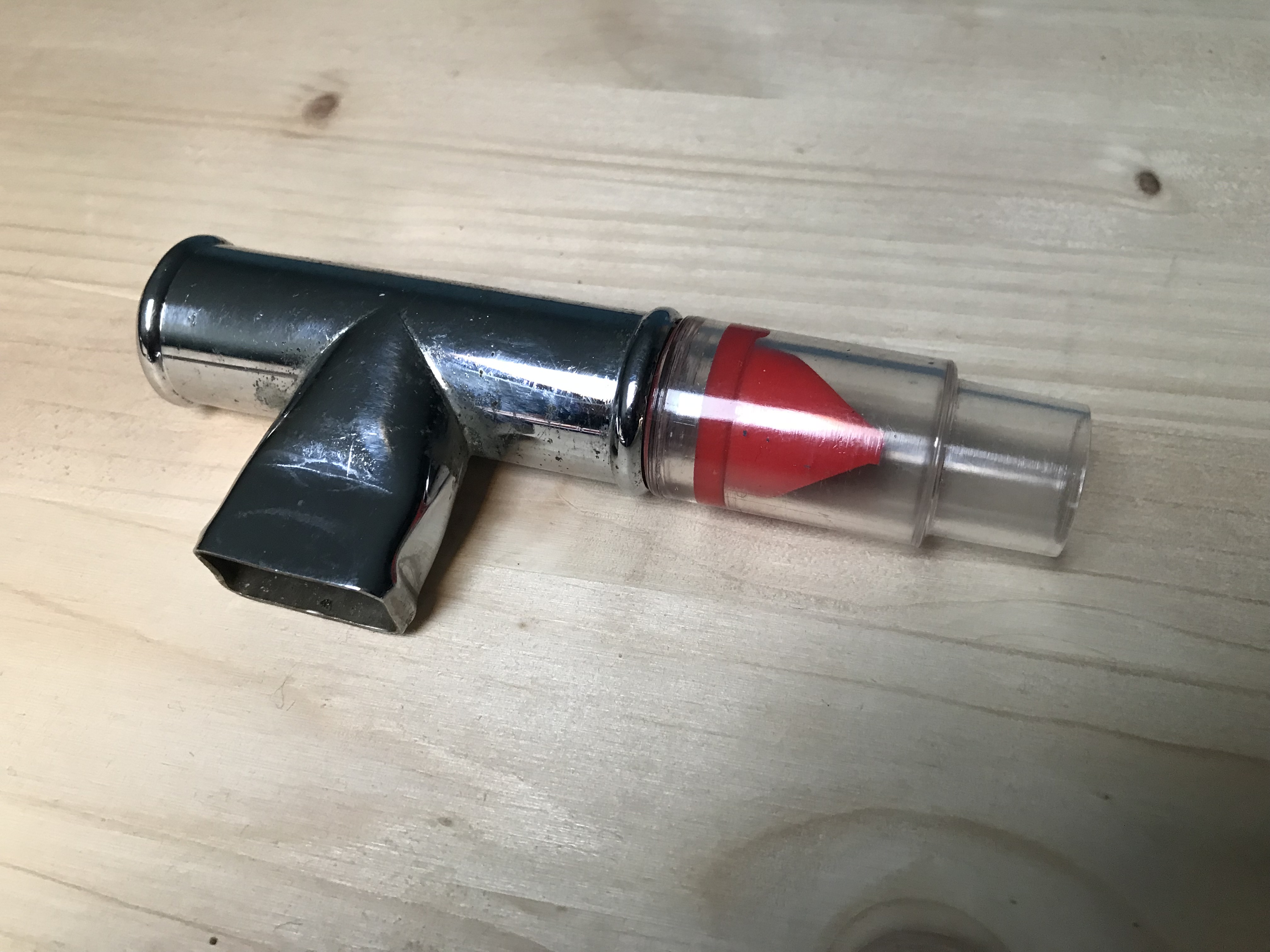
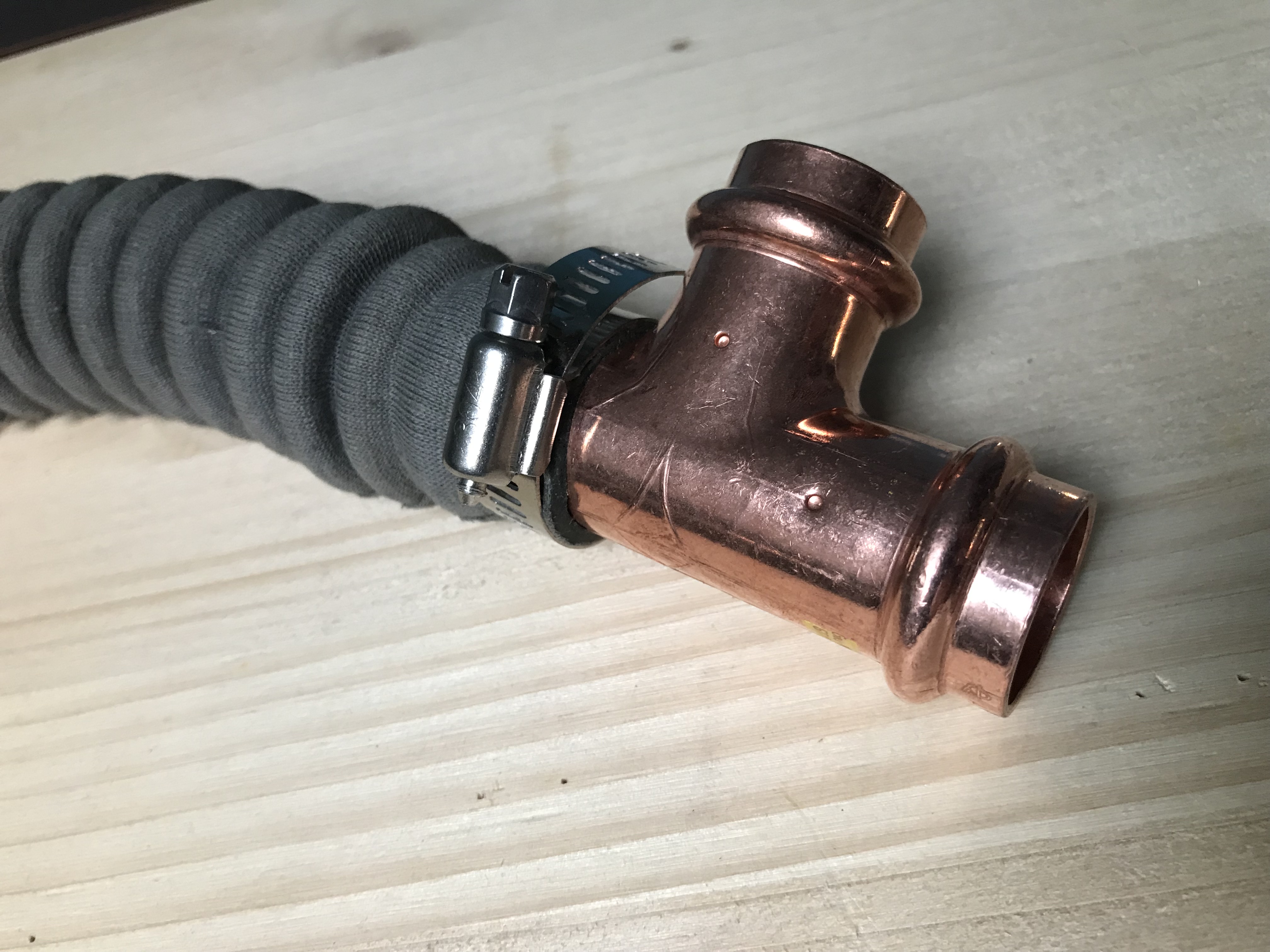
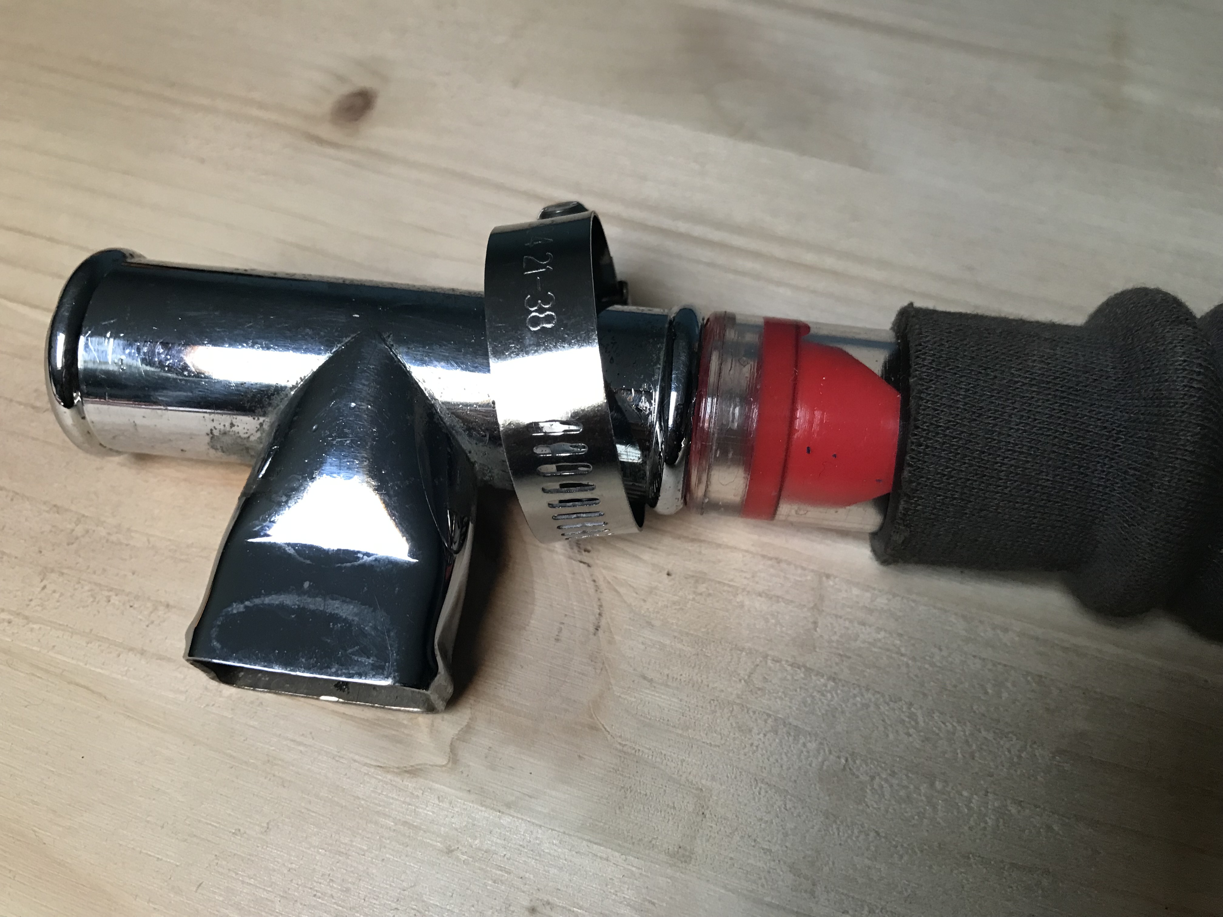
The corrugated rubber hoses with fabric covering, similar to those used in the breathing systems of military aircraft from which the AN-6004-1 type oxygen diluter was taken, were found in Latvia and are those used in the Russian type rebreathers IDA-71 and similar. Very robust and at reasonable cost. The copper T-fitting with 22 mm outlets diameter is one of those used for the assembly of pipes in homes heating systems and can be easily found at resellers of these materials. The other chromed T-piece is an old mouthpiece used in the first generation Mistral single-stage double hose regulator; a rubber mouthpiece will be mounted on this component and secured by a plastic tie strap. The two non-return valves with red rubber sealing elements and transparent plastic body, which are used in liquid and water distribution systems, are also available online. These valves, which we think can have an equivalent air-flow resistance, will replace the "flutter valves" of the article made by rubber "noisemakers" fitted on plastic spools. The sealing of these valves with the two T-fittings will be ensured by O-rings of suitable size mounted between the body of the valves and that of the T-fittings (see figs. 34, 35, 36 and 37).
 |
 |
| Fig. 34 |
Fig. 35 |
 |
 |
| Fig. 36 |
Fig. 37 |
The connection of the T-fittings with the corrugated hoses is secured by stainless steel screw metal clamps similar to those described in the article (see figs. 38 and 39).
 |
 |
| Fig. 38 |
Fig. 39 |
The final result of the assembly of the corrugated hoses with the mouthpiece and with the T-adapter for the connection with the oxygen diluter, can be seen in fig. 40.
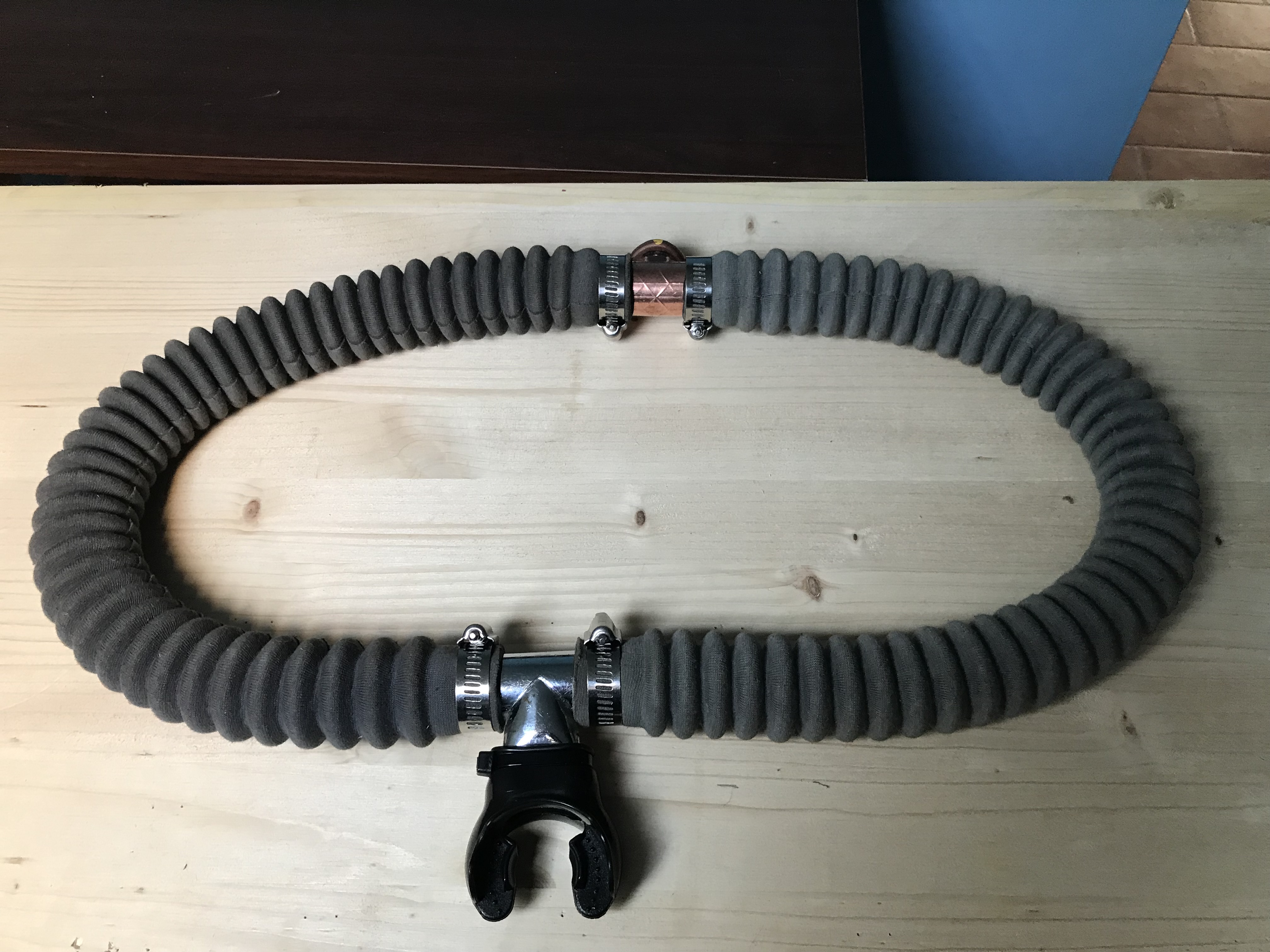 |
| Fig. 40 |
Final assembly
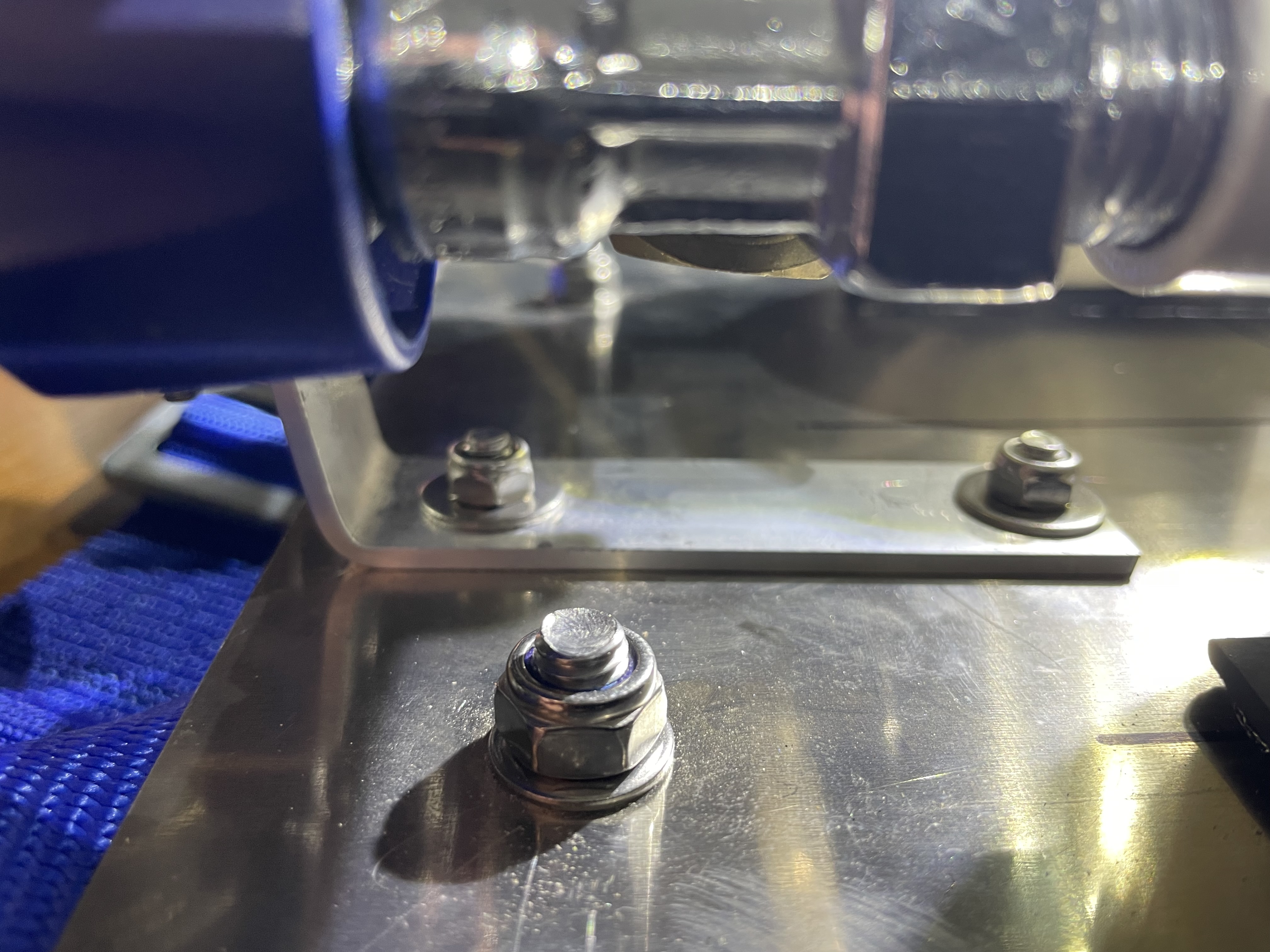
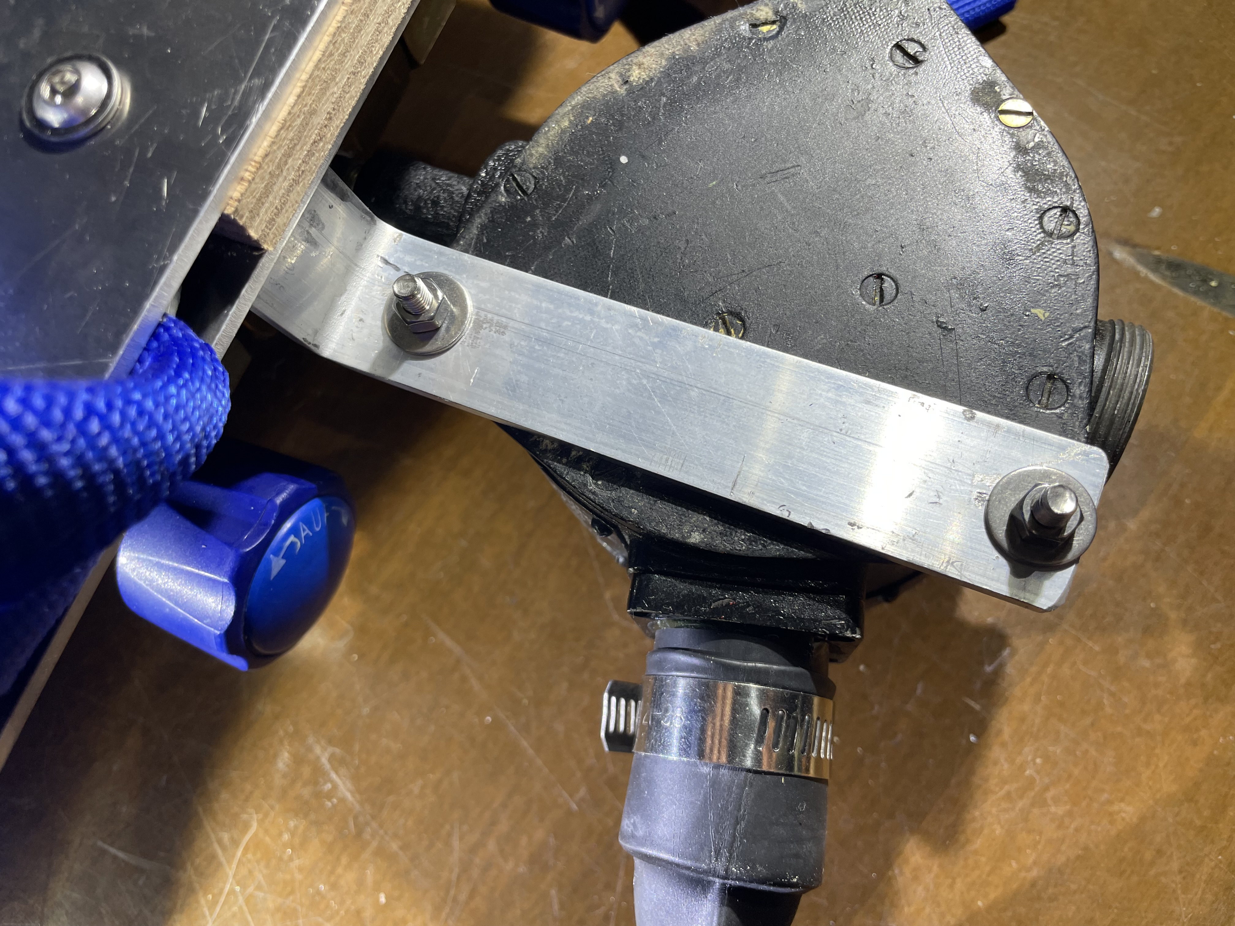
Finally, the breathing apparatus was completely assembled, also mounting the bracket for connecting the oxygen diluter body to the support plate, as described in the 1953 article (see figs. 41 and 42).
 |
 |
| Fig. 41 |
Fig. 42 |
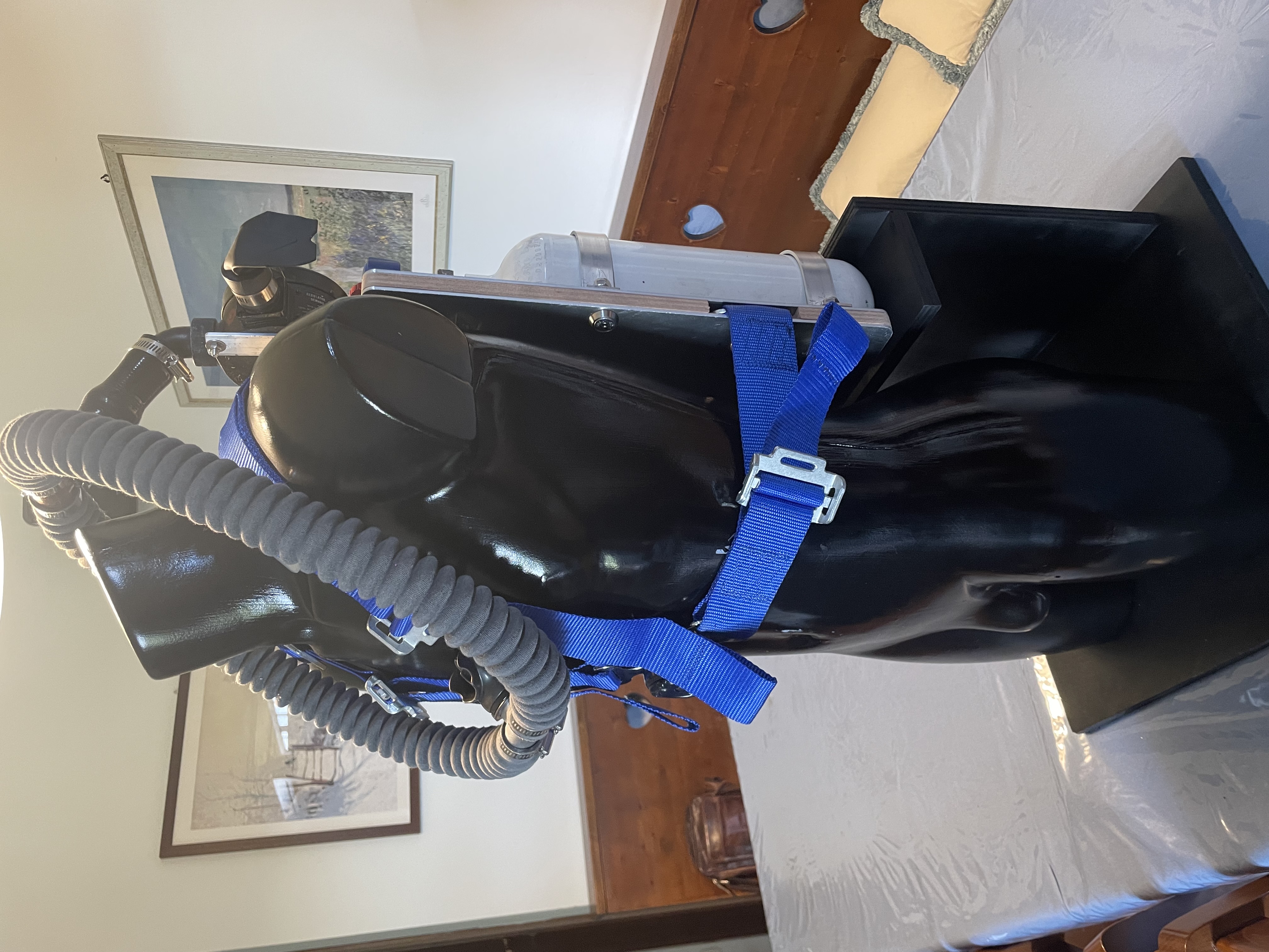
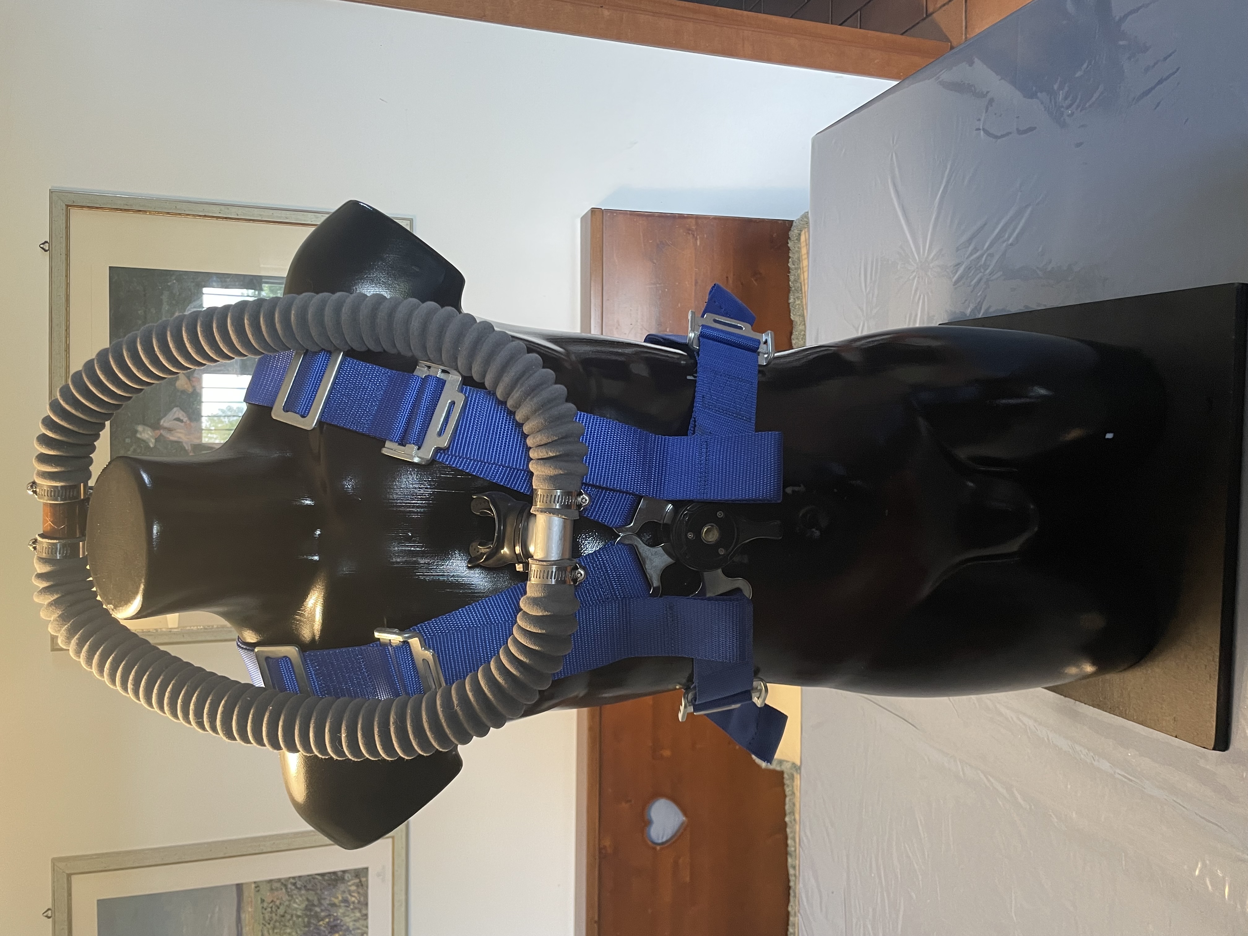
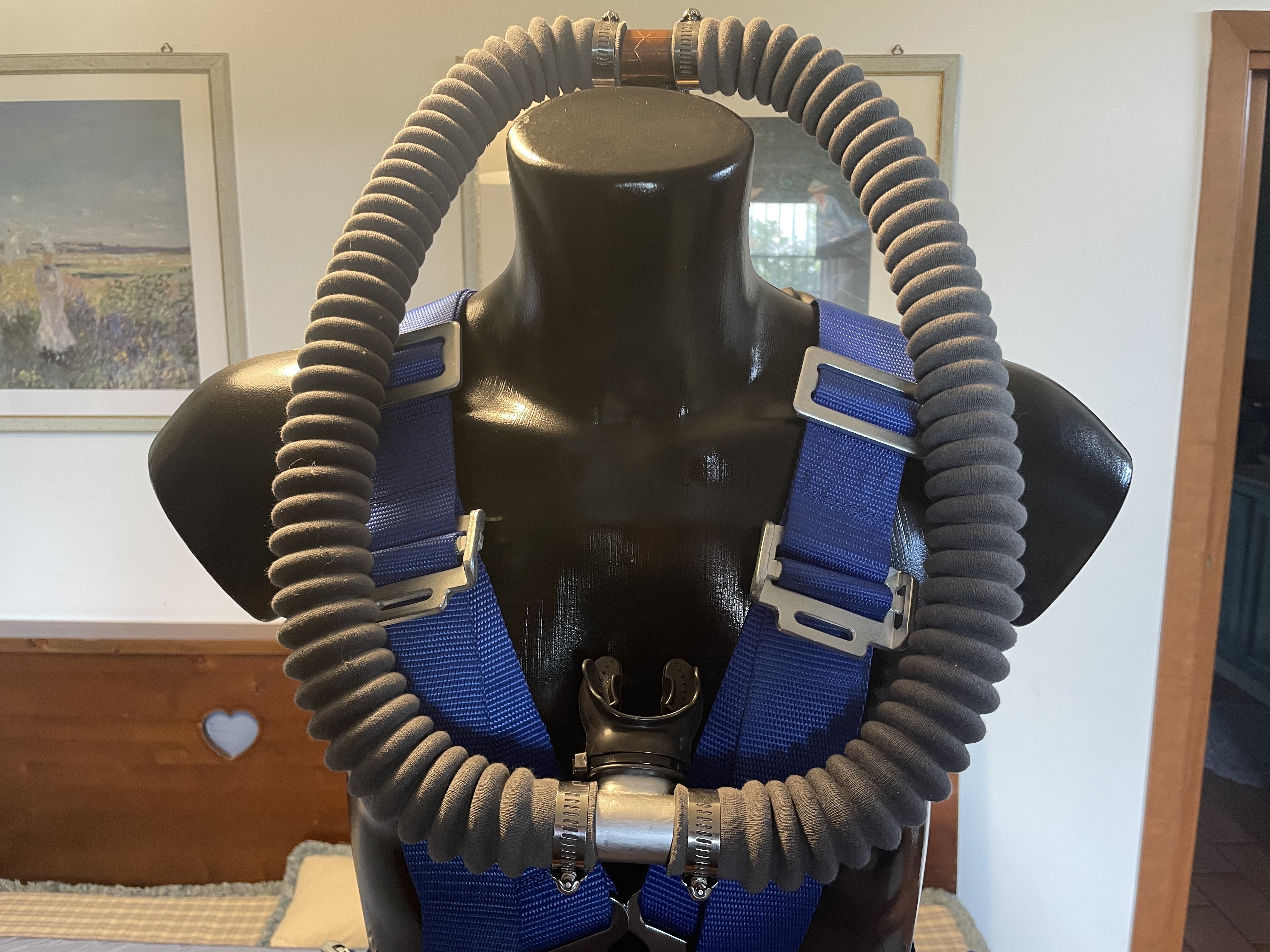
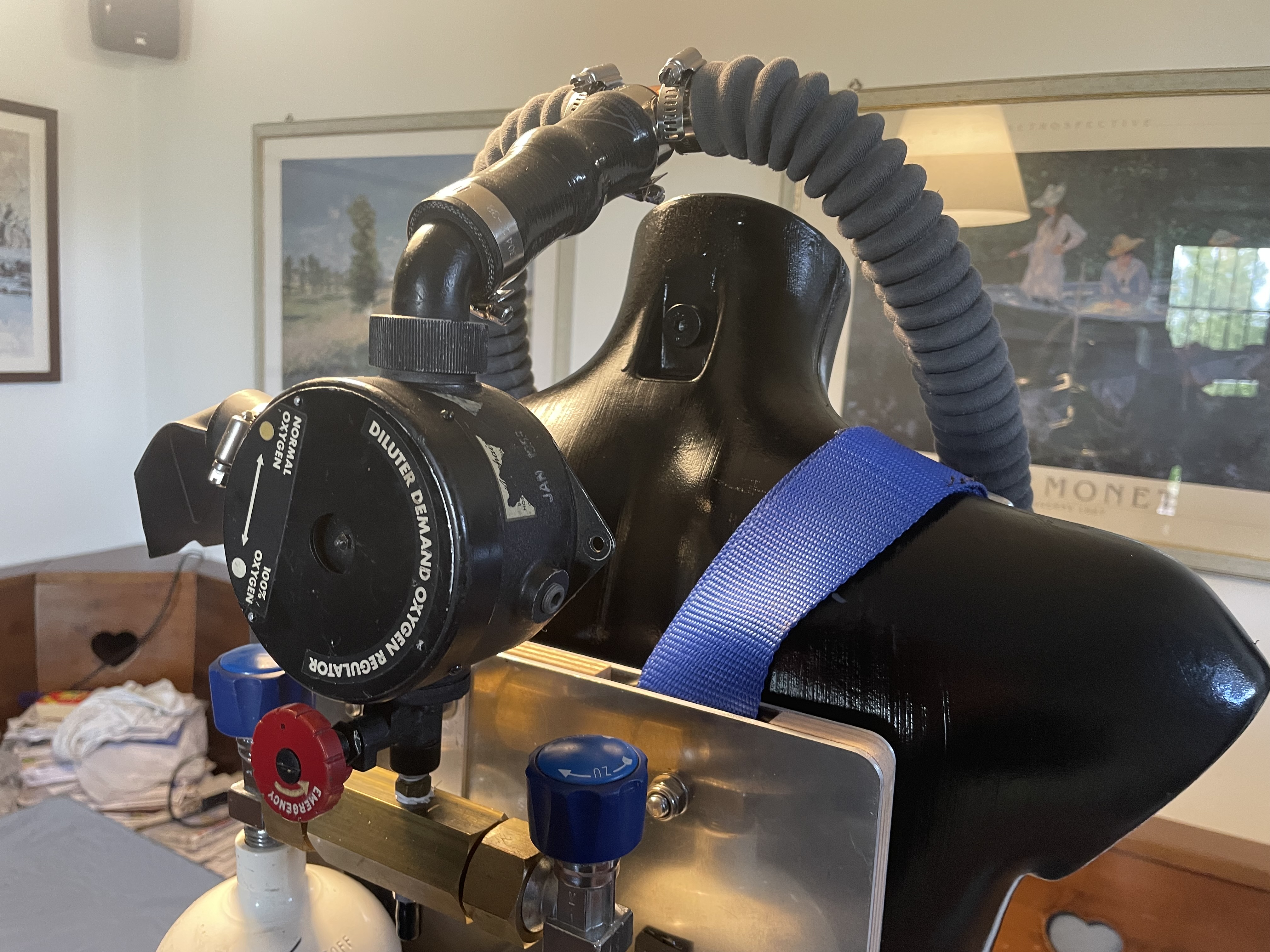
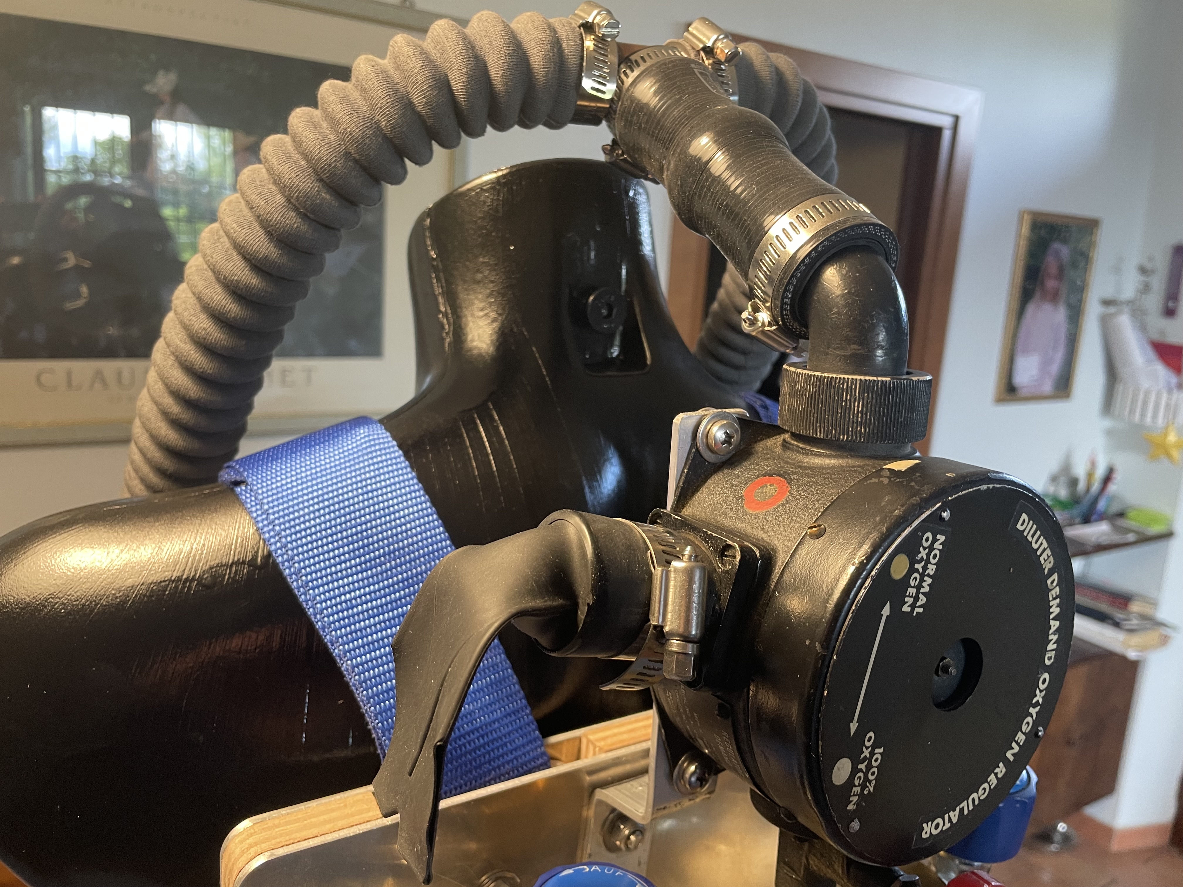
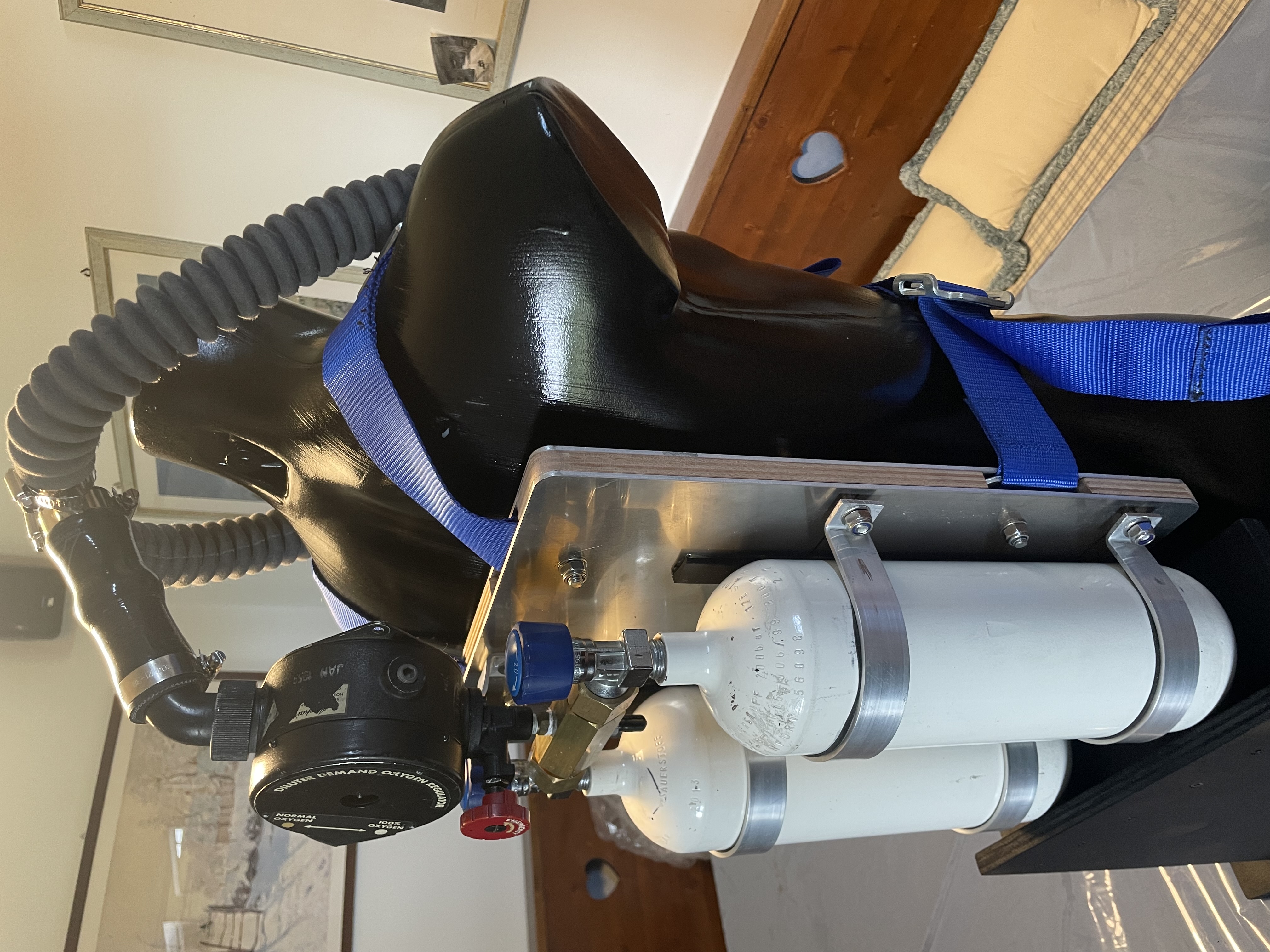
For the assembly I used stainless steel hardware consisting mainly of M5, M6 and M8 bolts with related washers and self-locking nuts. The final result, with the breathing unit installed on a dummy, is shown in figs. 43, 44, 45, 46, 47, 48, 49 and 50.
 |
 |
| Fig. 43 |
Fig. 44 |
 |
 |
| Fig. 45 |
Fig. 46 |
 |
 |
| Fig. 47 |
Fig. 48 |
 |
 |
| Fig. 49 |
Fig. 50 |
Following the publication of the article in Popular Science, there were even some companies, such as the Edward Aguado Trading Company (ATCO) of Saint Louis, which offered the complete kit and assembly instructions for sale, thus saving the purchasers the long work of research and acquire of the various components necessary for the building of this artisanal breathing apparatus. The selling price of these kits was $39.95 for the single-tank version and $49.95 for the double-tank version.
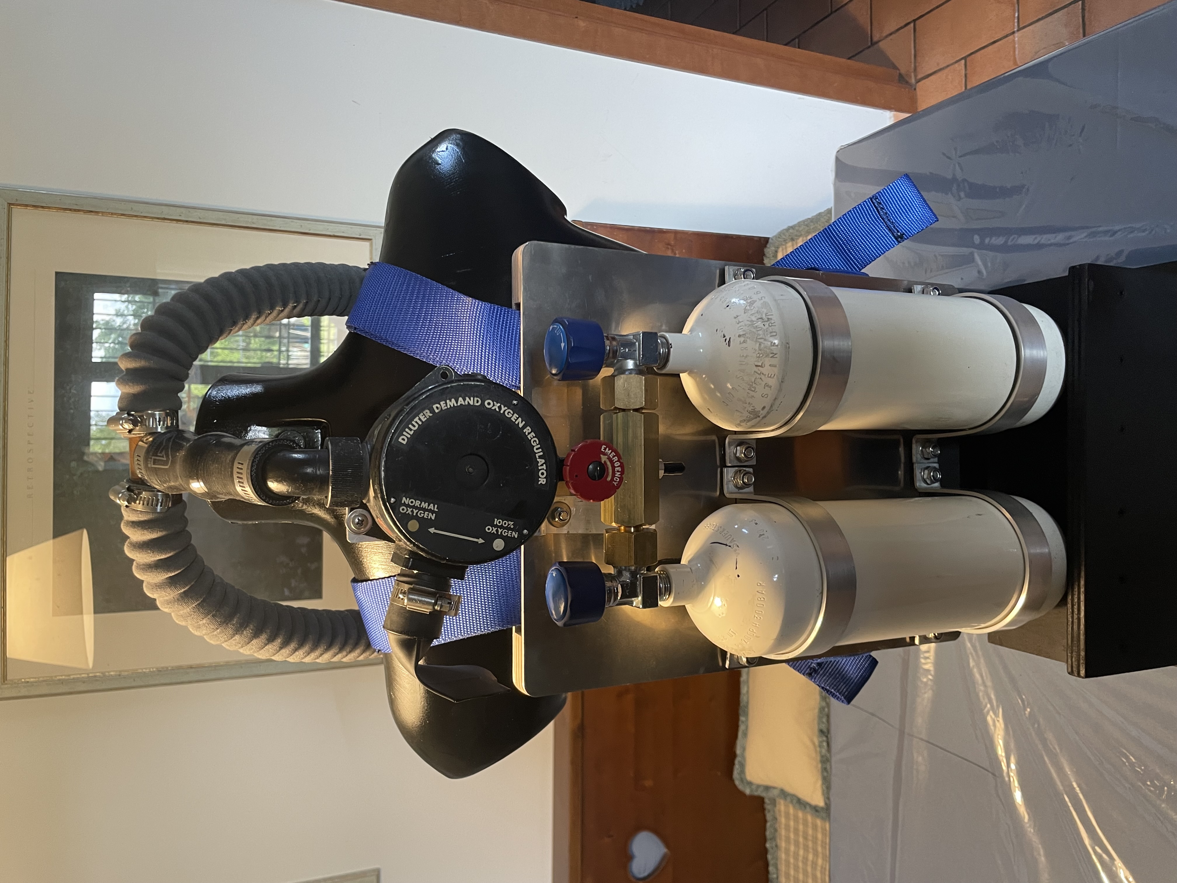
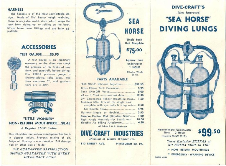
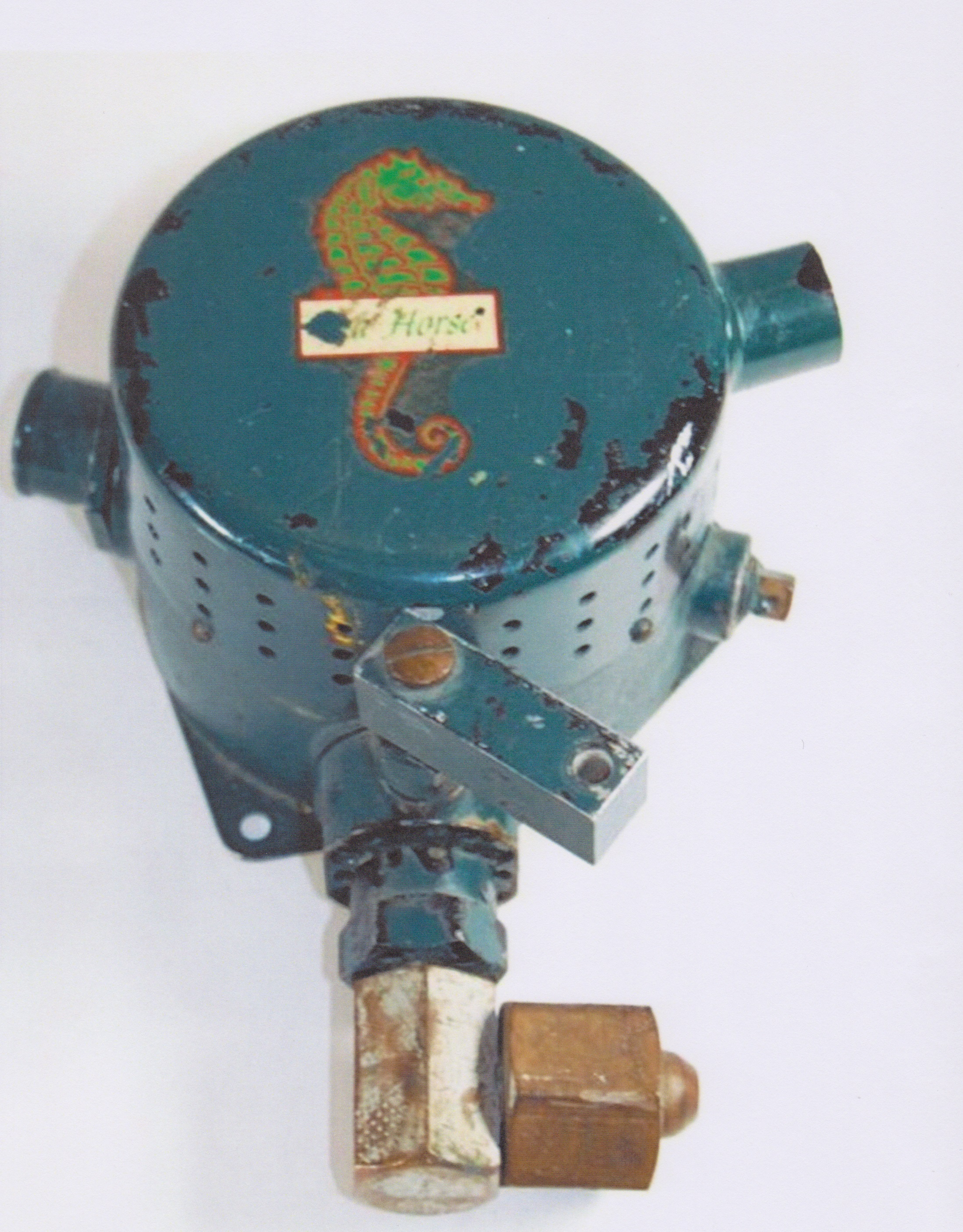
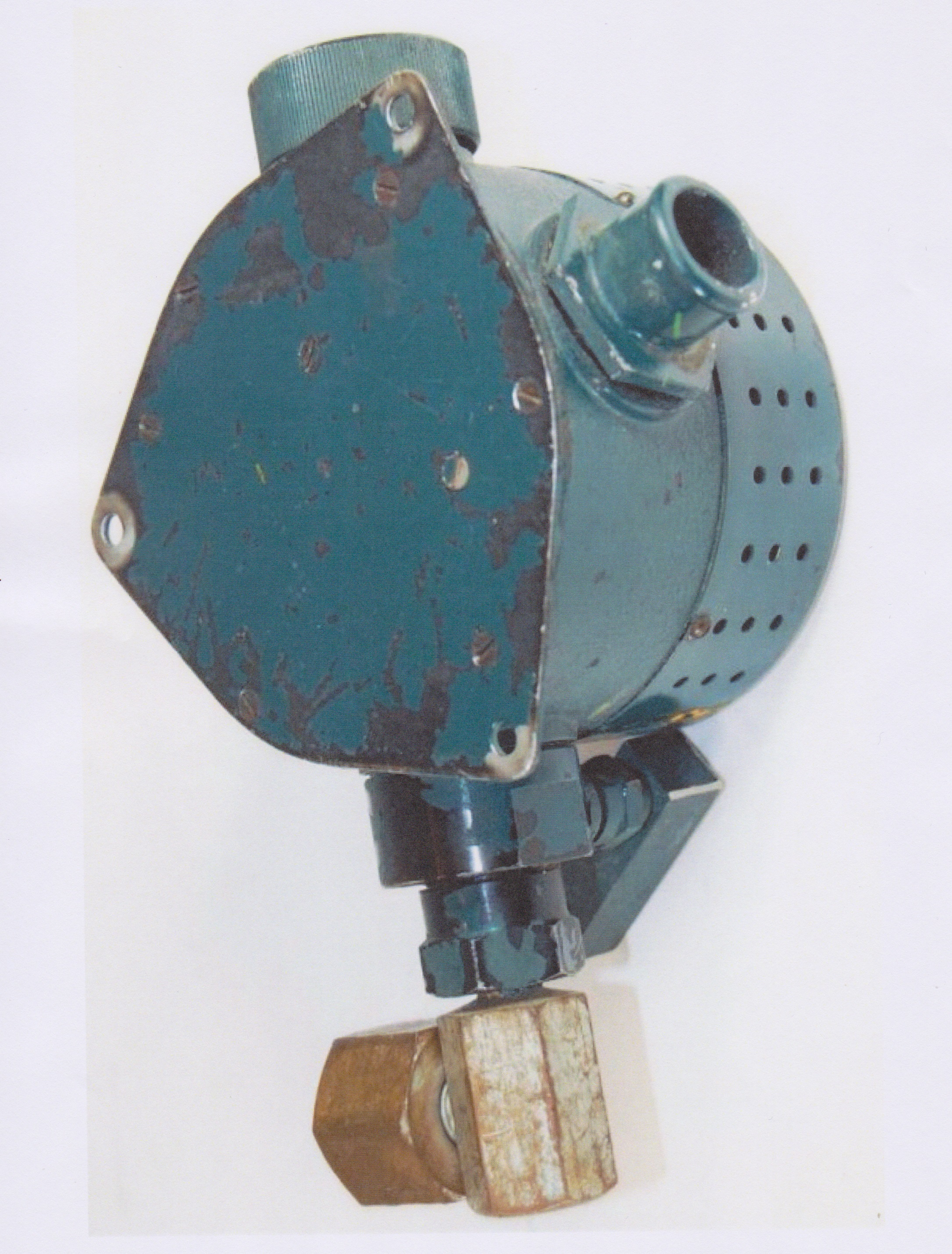
Other companies decided to convert these military devices though industrial proccesses and offer them on the market as an alternative to the more widespread and popular (but also much more expensive) SCUBA units. The most important of these was the Dive-Craft Industries of Pittsburgh (Pa) which would later become Diving Industries which, starting from 1952, began to distribute these SCUBA units derived from military oxygen diluters on the market under the name “Sea Horse Diving Lungs” (see figs. 51 and 52).
 |
 |
| Fig. 51 |
Fig. 52 |
As can be seen from the advertising brochure in fig. 51, the element of greatest attraction for the public was the price which remained significantly lower than that of the Cousteau Gagnan Aqua-Lung.
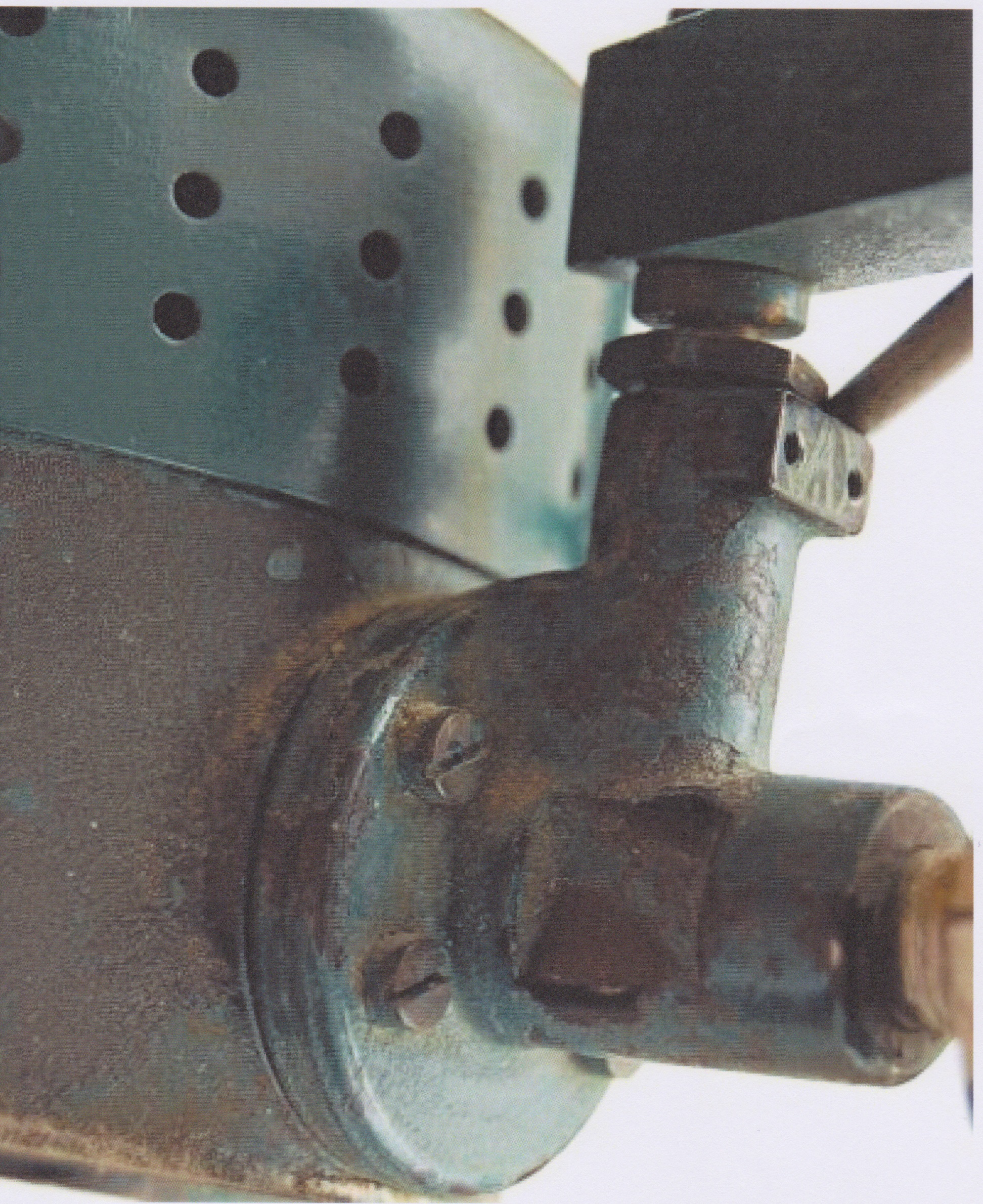
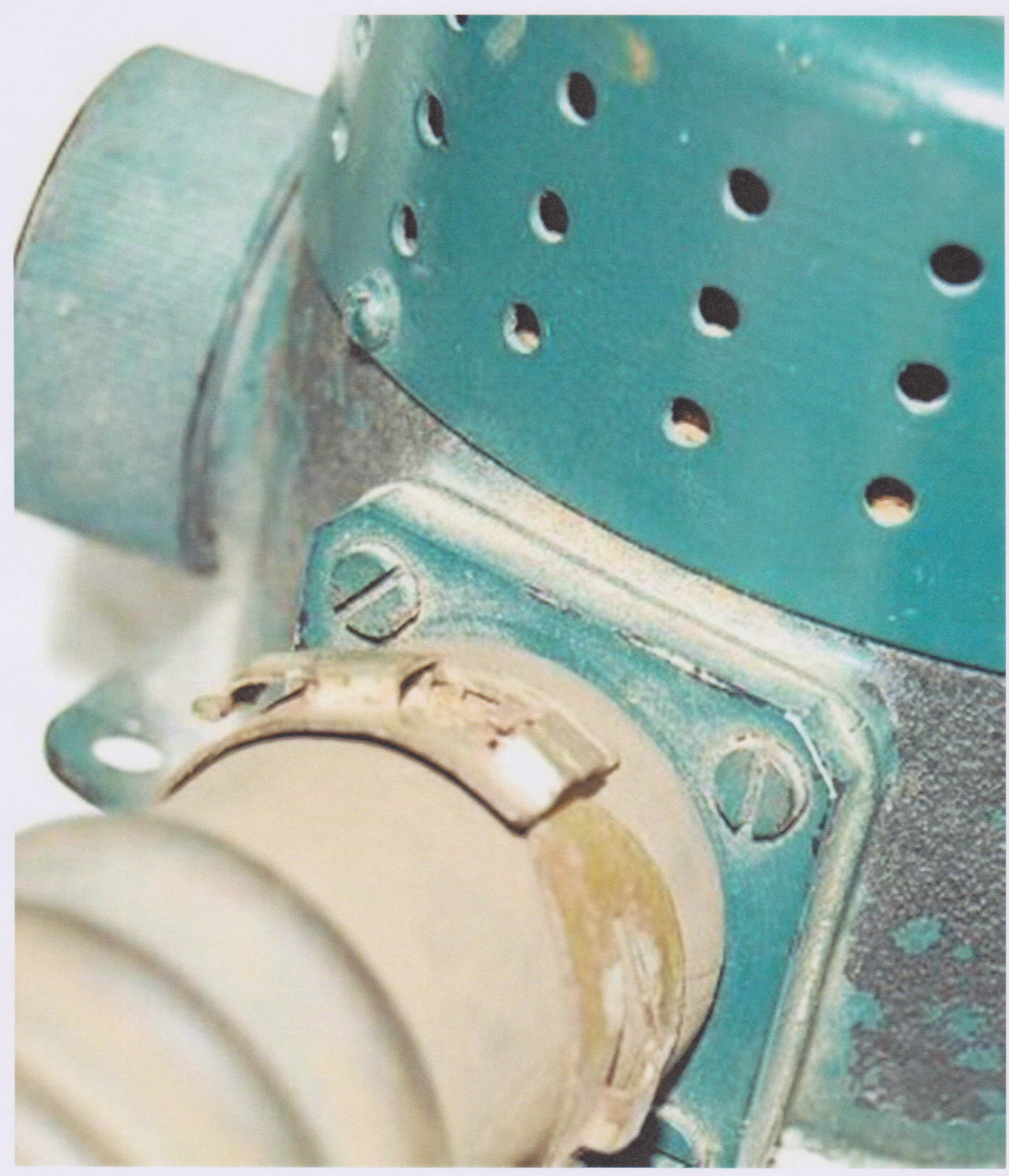
These "industrialized" versions had some significant modifications designed to mitigate some intrinsic limitations of the initial project, as described in the 1953 article. The most important modification consisted in the separation between the inhalation and the exhalation circuits which, starting from T-fitting connecting the corrugated hoses, really was of the pendular type. That is, the air flowed in two opposite directions during the inhale and exhale breathing cycle inside the same part of the circuit with a significant accumulation of carbon dioxide. Furthermore, the initial configuration of the device, with the exhaust circuit in communication with the inside of the oxygen diluter, made it frequent to be contaminated with salt water with a consequent strong acceleration of the corrosion of its internal mechanisms. The solution adopted by the US company consisted in replacing the original cover of the oxygen diluter unit with a bigger one where the duckbill exhaust valve and the related outlet connection could be installed. In addition, to obtain a better overall layout of the breathing circuit, the exhalation outlet was also moved from the 45° oriented fitting of the oxygen diluter unit to the modified fitting where the duckbill valve was installed in the original version. At that point even the 45° fitting itself became useless and was therefore eliminated and replaced with a cap. Finally, the red knob for regulating the oxygen flow was also replaced with a lever mechanism which made it much easier for the diver to operate the valve. Said modifications are shown in figgs. 53, 54, 55, 56, 57 and 58.
 |
 |
| Fig. 53 |
Fig. 54 |
 |
 |
| Fig. 55 |
Fig. 56 |
 |
 |
| Fig. 57 |
Fig. 58 |
Despite the improvements introduced in the commercial versions, the performance of this self-contained breathing apparatus always remained very poor, especially from the point of view of breathing efforts and the air flow rate actually available. The author of the article himself recommended its use for depths no greater than 30 feet (about 9 meters). This conclusion should not surprise us if we consider that the military oxygen diluter unit was designed to operate at ambient pressures not exceeding 1 bar and that much of the gas flow rate delivered in most conditions was taken directly from inside the aircraft cabin. Despite its recognized limitations and its aesthetic appearance certainly not comparable to that of much more famous and expensive models already available on the market in that period, this type of breathing apparatus, which remained in production for only a few years (1957), still represents a key milestone in the history and evolution of SCUBA equipment during the pioneering phase of diving.